Color Computer Technical Reference Manual

Information for Programmers and Technicians

Front cover


Table of contents

SECTION
NUMBER
PAGE
NUMBER
   

I INTRODUCTION

System Description........................................... 2
System Block Diagram - Illustration ......................... 3
Memory Map................................................... 4

II DISASSEMBLY/ASSEMBLY

Disassembly ................................................ 12
Reassembly ................................................. 12
Disassembly/Reassembly - - Illustration .................... 13

III THEORY OF OPERATION

6809E CPU................................................... 16
6809E Block Diagram - Illustration ......................... 16
6809E Programming Model - Illustration ..................... 17
6809E Typical Timing of Read/Write Cycles - Illustration ... 18
Reset Circuit .............................................. 17
Dynamic Memory Control ..................................... 19
MC6883 Block Diagram - Illustration ........................ 20
Timing Diagram - - Illustration ............................ 21
ROM ........................................................ 21
Video Interface ............................................ 21
Mode Selection - - Table 1 ................................. 24
Description of Display Modes - - Table 2 ................... 25
Display Character Set - - Table 3 .......................... 27
VDG Video Output - Illustration ............................ 28
MC1372 Block Diagram - - Illustration ...................... 28
Video Input to the Modulator - Illustration ................ 29
PIAs ....................................................... 29
PIA Block Diagram - Illustration ........................... 29
Digital to Analog (D/A) .................................... 30
Joystick Interface ......................................... 30
Sound Output ............................................... 31
Sound Selection - Table 4 .................................. 31
Sound Circuity - Illustration .............................. 31
Cassette Interface ......................................... 32
Sample Data of Cassette Format - Illustration .............. 32
Tape Format Information .................................... 32
RS232C Interface ........................................... 33
RS232 Connector Pin-out - Illustration ..................... 33
Keyboard Interface ......................................... 33
System Power Supply ........................................ 33
723 Regulator Block Diagram - Illustration ................. 34
Cartridge ROM and Other Devices ............................ 35
Cartridge Connector Signals - Table 5 ...................... 36
ROM Cartridge Board Schematic - Illustration ............... 37
RS232 Devices .............................................. 38
Line Printer Variables - Table 6 ........................... 38
Alternate Line Printer Variables - Table 7 ................. 39
Joysticks .................................................. 40
Joystick Schematic - Illustration .......................... 40
TV Switch Box .............................................. 41
Antenna Switch Box Schematic - Illustration ................ 41

IV TROUBLESHOOTING

Fault Isolation............................................. 44
Diagnostic Notes ........................................... 44
Video Interface ............................................ 44
Joystick Interface.......................................... 45
Cassette Interface...... ................................... 45
Keyboard Interface.......................................... 45
RS-232 Interface ........................................... 45
Power Supply ............................................... 46
Power Supply Voltage Levels - Illustration.................. 47

V PARTS LISTS

Printed Circuit Board Parts List........................... 50
Illustrated Parts Breakdown ............................... 56
Illustrated Parts Breakdown - Illustration................. 57

VI PRINTED CIRCUIT BOARD

Printed Circuit Board - - Component Side .................. 60
Printed Circuit Board - Circuit Side ...................... 61

VII SCHEMATIC

Color Computer Schematic - Sheet 1 .................... 64, 65
Color Computer Schematic - Sheet 2 .................... 66, 67
Color Computer Schematic - Sheet 3 .................... 68, 69

Color Computer Technical Reference Manual:
Copyright © 1981 Tandy Corporation,
Fort Worth, Texas 76102, U.S.A.
All rights reserved.

Reproduction or use, without express written permission from Tandy Corporation, of any portion of this manual, is prohibited. While reasonable efforts have been taken in the preparation of this manual to assure its accuracy, Tandy Corporation assumes no liability resulting from any errors or omissions in this manual or from the use of the information obtained herein.

Portions of this manual were reproduced, with express written permission from the Motorola Corporation, from the following Motorola data sheets:

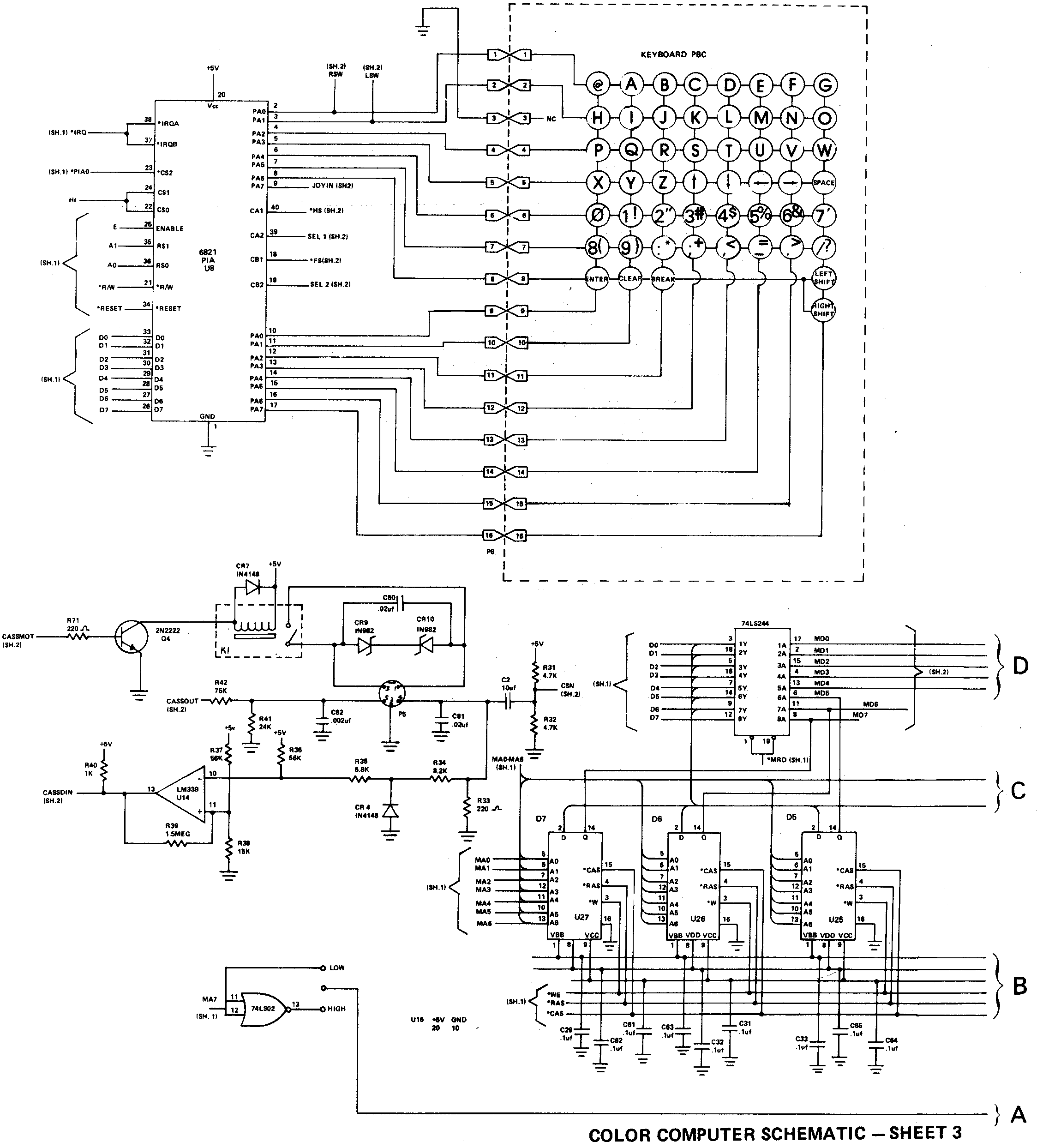
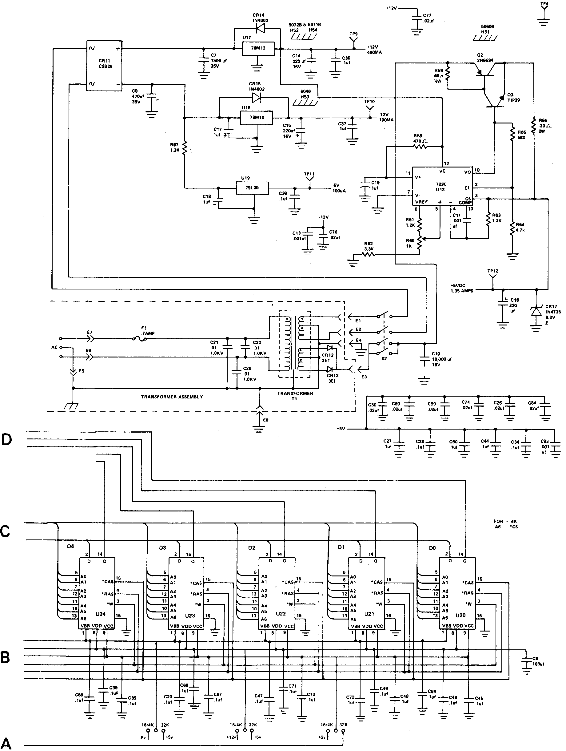
ADI-492R2
ADI-847
ADI-595
DS9435 R1
DS-9522
MC6847
MC6809E
MC6883
MC6821
MC1372

This manual was written by Dale Chatham, and edited by Sandra Williams

Printed in the United States of America


IMPORTANT NOTICE

This Technical Reference Manual is written for owners of the TRS80 Color Computer, who have a thorough understanding of electronics and computer circuitry. It is not written to the beginner’s level of comprehension.

Radio Shack will not be liable for any damage caused, or alleged to be caused, by the customer or any other person using this technical manual to repair, modify, or alter the TRS80 Color Computer in any manner.

Many parts of the computer electronics are very sensitive and can be easily damaged by improper servicing. We strongly suggest that for proper servicing, the computer be returned to Radio Shack.

Because of the sensitivity of computer equipment, and the potential problems which can result from improper servicing, the following limitations apply to services offered by Radio Shack:

1. If any of the warranty seals on any Radio Shack computer product are broken, Radio Shack reserves the right to refuse to service the equipment or to void any remaining warranty on the equipment.

2. If any Radio Shack computer equipment has been modified so that it is not within manufacturer’s specifications, including, but not limited to, the installation of any non-Radio Shack parts, components, or replace-ment boards, then Radio Shack reserves the right to refuse to service the equipment, void any remaining warranty, remove and replace any non-Radio Shack part found in the equipment, and perform whatever modifications are necessary to return the equipment to original factory specifications.

3. The cost for the labor and parts required to return the Radio Shack computer equipment to its original specifications will be charged to the customer in addition to the normal repair charges.