Color Computer Technical Reference Manual
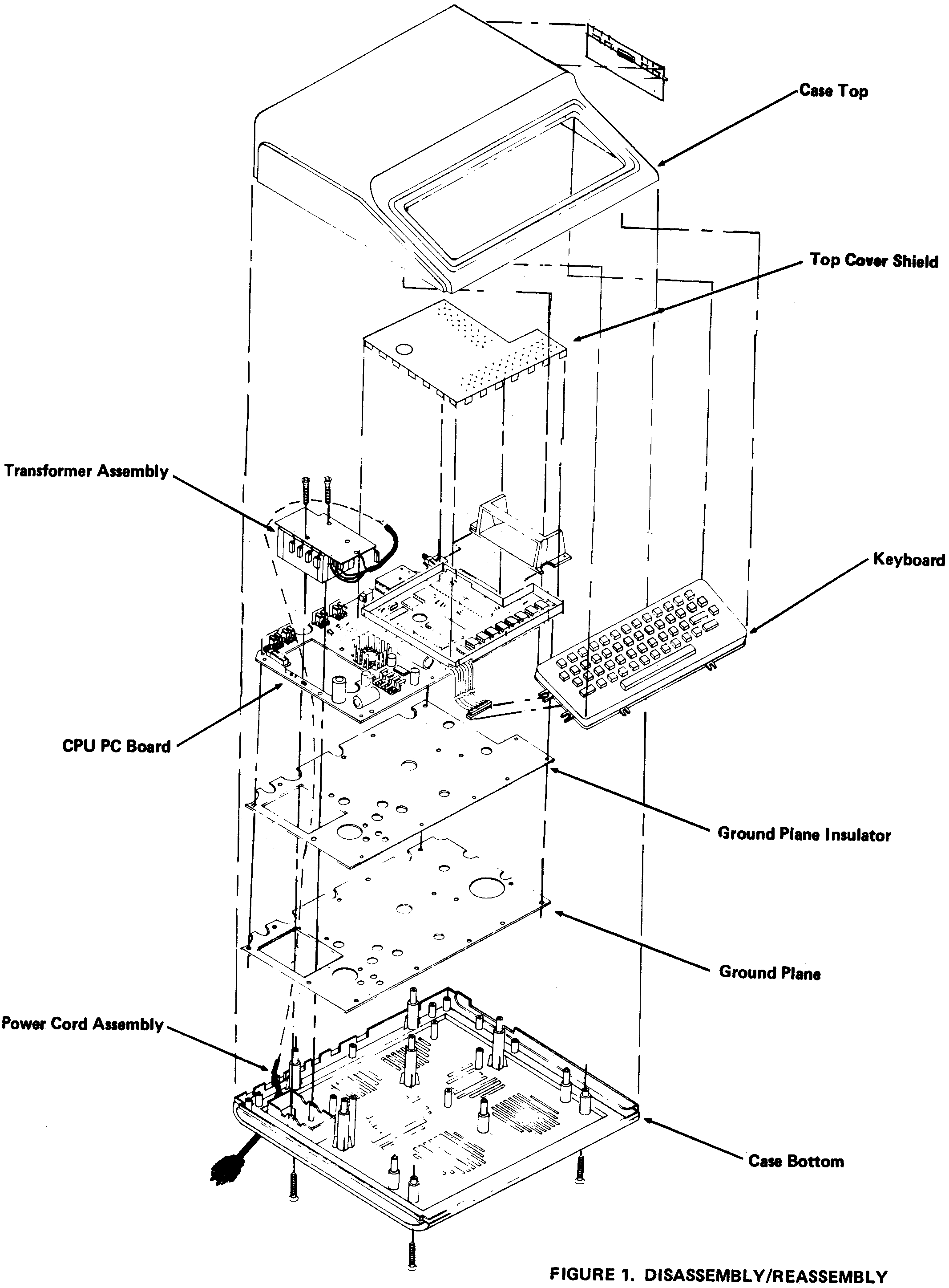
DISASSEMBLY1. Make sure all cables (also power cord) are disconnected. Place the Color Computer face down on a padded or non-scratching surface and remove the seven screws from the Case Bottom. (Because the screws are positioned so deeply, you may not be able to actually remove them until the Computer is turned face up.) 2. Carefully place the Computer face up and lift off the Case Top and set it aside. 3. Carefully lift the Keyboard off the plastic bosses and remove the Keyboard Cable 4. Remove the Top Cover Shield and set it aside. You may have to remove the top cover of the modulator (U5) to get the shield off. 5. Remove the three screws supporting the transformer assembly (two on transformer, one on the board) and disconnect all jumper cables. 6. Remove the ten screws fastening the CPU PC Board and lift the Board off its plastic bosses. 7. Remove the Ground Plane and Insulator from the back of the PC Board by using a screwdriver or other small, thin tool to pry off all sixteen fasteners from the rear of the Board. |
REASSEMBLY1. Replace the Ground Plane and its Insulator on back of the PC Board and install the sixteen fasteners. You may need some pliers to close the tips together and then insert. 2. Replace the PC Board onto the plastic bosses. Be sure that the ends of the Power Cord are pulled through the square cutout in the Board where the transformer is positioned. 3. Fasten the PC Board in place using ten #6 x 1/2* screws. 4. Connect the transformer jumper cables, E1 through E4 and the Power Cord jumpers, E6 - white, E5 - green, and E7 - black. 5. Position the Transformer assembly and attach jumper cable E8. Fasten using two #6 x 1 1/2* screws (on transformer) and one #6 x 1/2* screw (on board). 6. Replace the Top Cover Shield. 7. Reconnect the Keyboard Cable and Cable Shield if used. Replace the Keyboard onto the plastic bosses in the case bottom. 8. Replace the Case Top onto the Case Bottom and carefully turn the entire unit over (face down). 9. Replace the seven screws in the Case Bottom (two #6
x 7/8* toward the front and five #6 x 1 1/4* toward the
rear). Do not put the longer screws in the front
positions, it could dent the Computer Case Top. |