Document Ref: VDUK-1/2
Issue: 1.2
Date: October 1982
(Reprinted May 1983)
Copyright Note:
No unauthorised copies of this manual may be made.
© 1982 Greenbank Electronics
Manual Price £2.00
PAGE 1-1
This is a card produced especially for the Interak 1 computer.
It is an 'Applications' card, in that it is designed to permit low cost applications of computer displays using a standard domestic. TV receiver, whilst still retaining high quality.
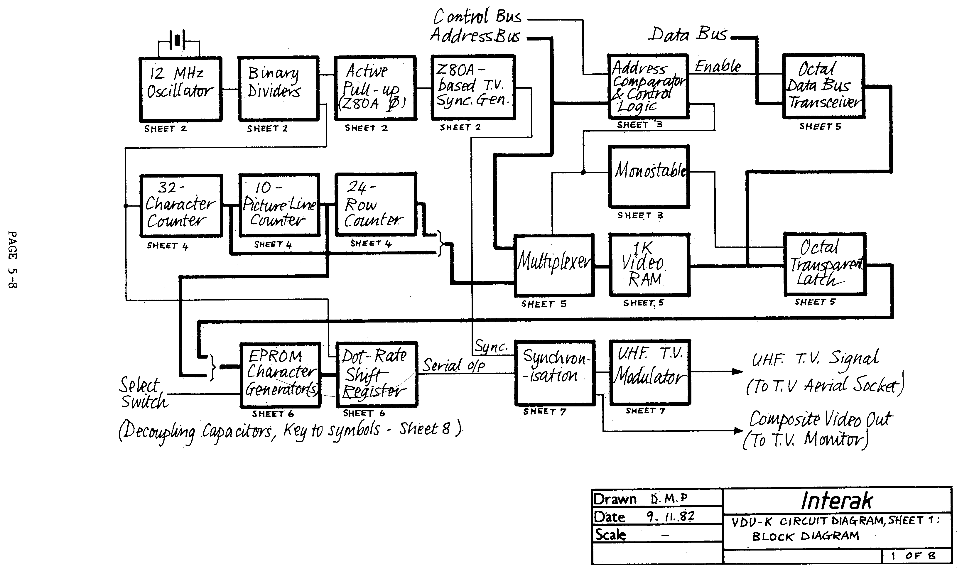
Many diverse applications are possible due to the fact that the character set used is held in EPROM and thus may be specified to suit the particular application.
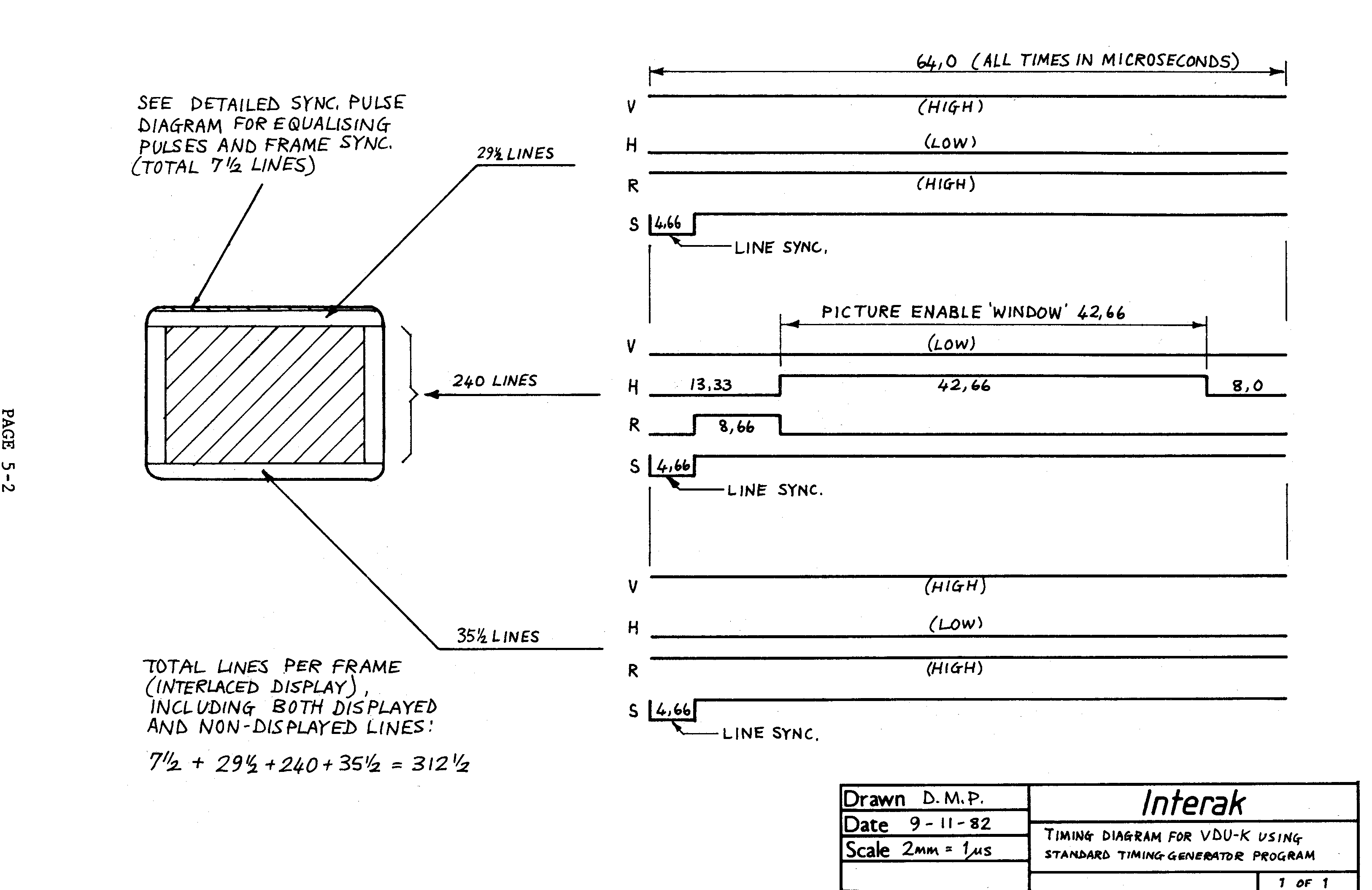
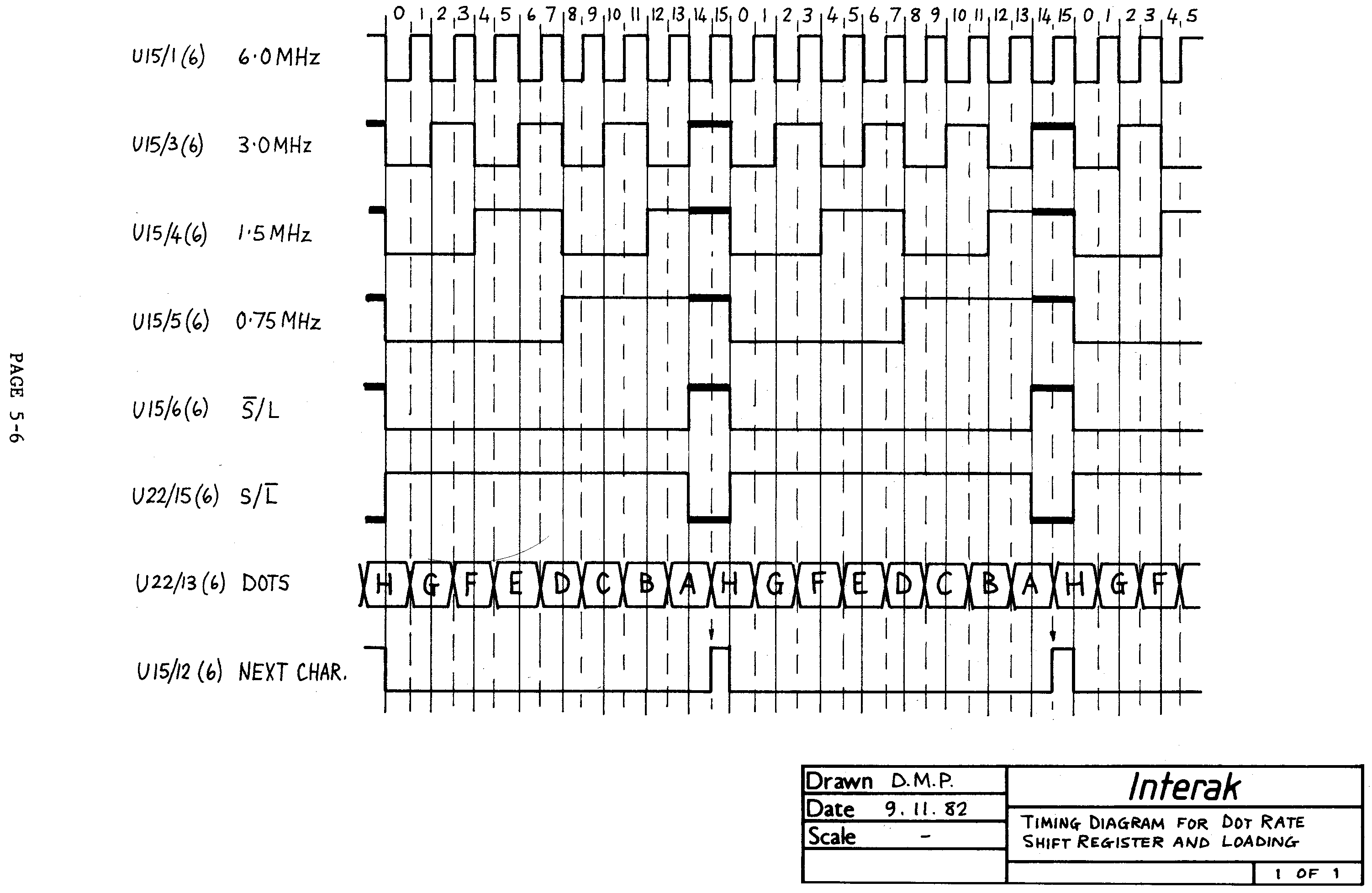
A very low dot clock (6 MHz) has been used, which is the secret of obtaining a high quality display on an ordinary TV receiver, and various design refinements have been incorporated (e.g. generation of proper TV sync. pulse waveforms, provision of choice of interlaced / non-interlaced display) to ensure that the card can be used with confidence in its chosen application.
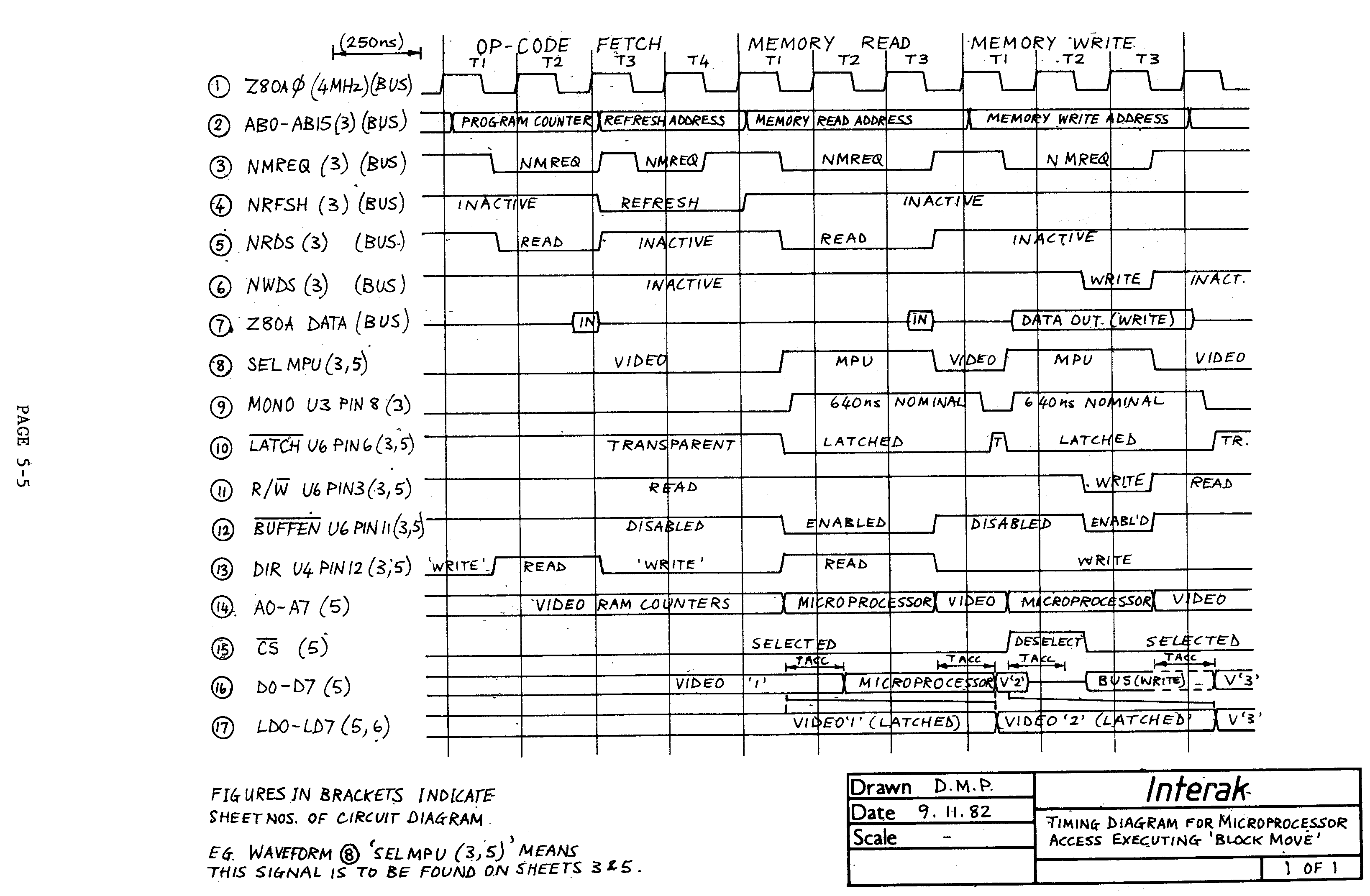
The outstanding feature is the avoidance of "snow", (the interference effect which is often seen in low-cost designs when the microprocessor accesses the screen during the display time). In consequence this board is ideally suited for very fast animated displays.
The screen format employs characters of a good size which are approximately square, and so it is very easy to make a display which aesthetically is very pleasing.
One application for which the card is less suited is that in the "professional" and "business" worlds, in those applications where one user wishes to view large quantities of alphanumeric data or text. In such an application the ability to produce fast animations viewable by a group of people is less important; there is a fair amount of truth in the statement that it is only necessary to fill a screen with text at a rate which is faster than it can be read and high speed of access is only a luxury.
It is anticipated that for word-processing etc. applications some alternative to the VDU-K will become available in the Interak range, but as serious word-processing etc. often goes hand in hand with the use of relatively expensive floppy disks and VDU terminals, it is likely that there will always be a place for the VDU-K in a low-cost system. (Note however that the "Interaktion" Users Group has details of a fairly simple modification to permit 64 characters on the VDU-K, although this is at the expense of the "no snow" feature. See User Group Newsletter Number 2, March 1983.)
PAGE 1-2
1.1 Title Page, Copyright Note
1.2 Preface
1.3 Contents
1.4 Errata
1.5 MOS Devices - Precautionary Notice
1.6 MOS Handling Precautions
1.7 General Features
2.1 Introduction
2.2 General Description
2.3 Switch Settings, EPROMs, Options, etc..
2.4 Detailed Circuit Description
3.1 Constructional Notes
3.2 Testing/Setting Up
3.3 Fault Finding, Return for Service
4.1 ASCII Character Set & Standard Characters
4.2 Character Generator EPROMs
4.3 Timing Generator EPROM
4.4 VDU Memory Map (for Interak 1)
4.5 Interlaced/Non-Interlaced display
4.6 Effect of A.C. Coupling in Video Circuits
5.1 Bus Signals 5-1
5.2 Timing Diagrams 5-2, 5-3, 5-4, 5-5, 5-6
5.3 Drilling Diagram 5-7
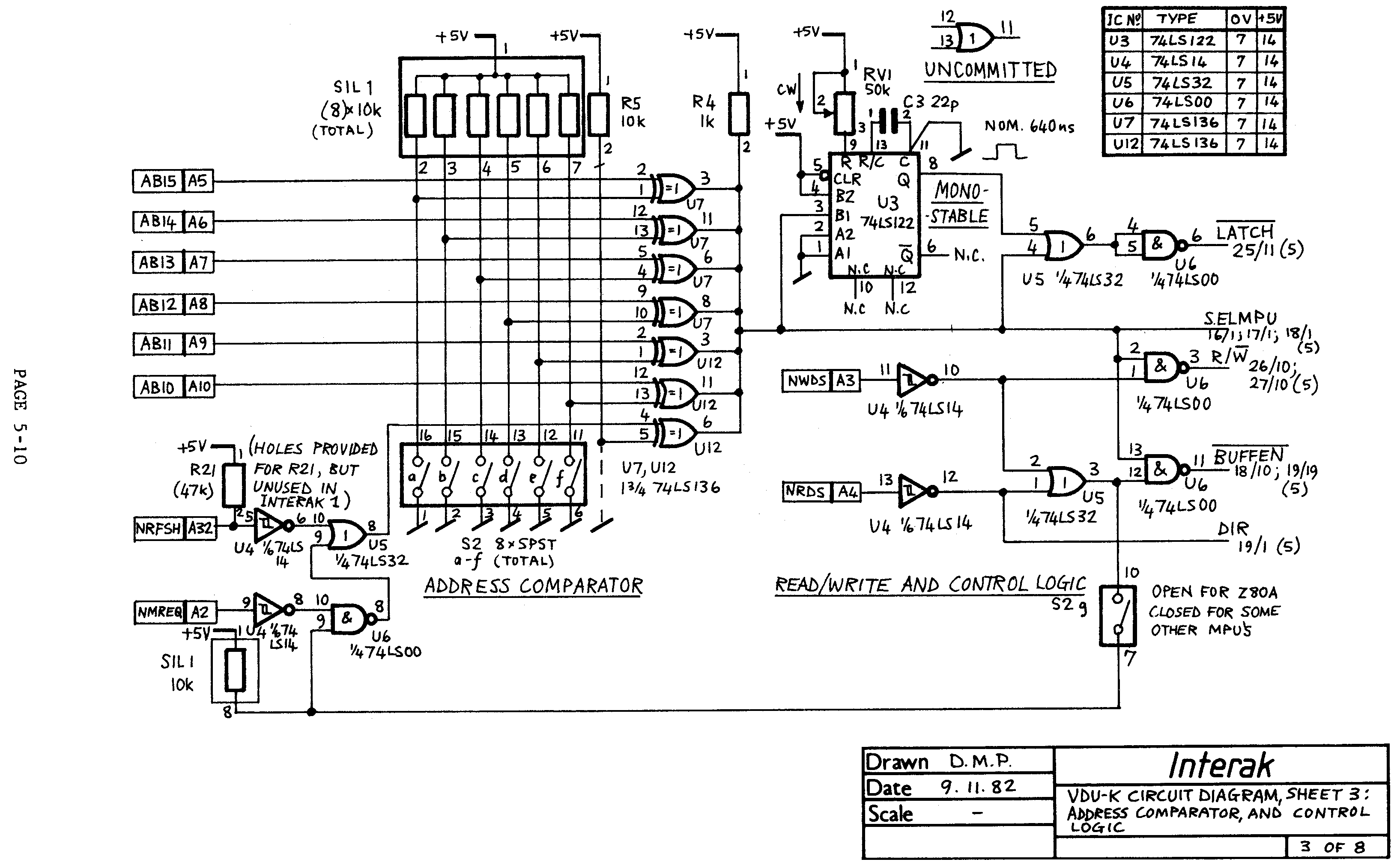
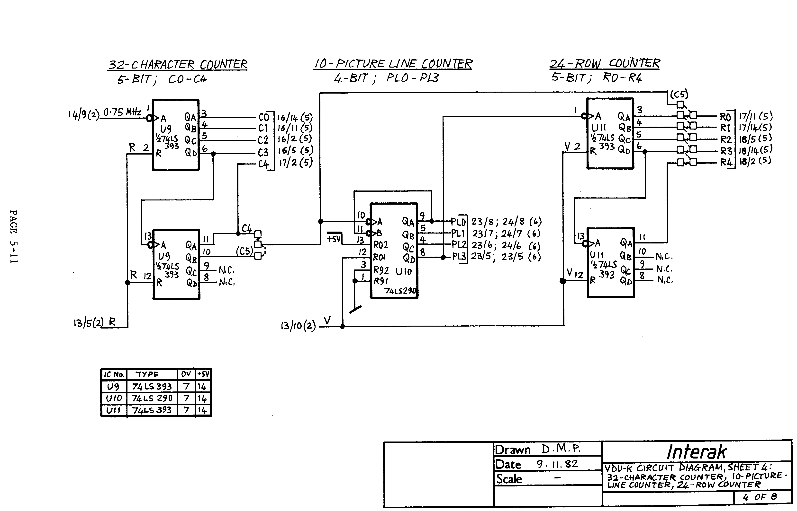
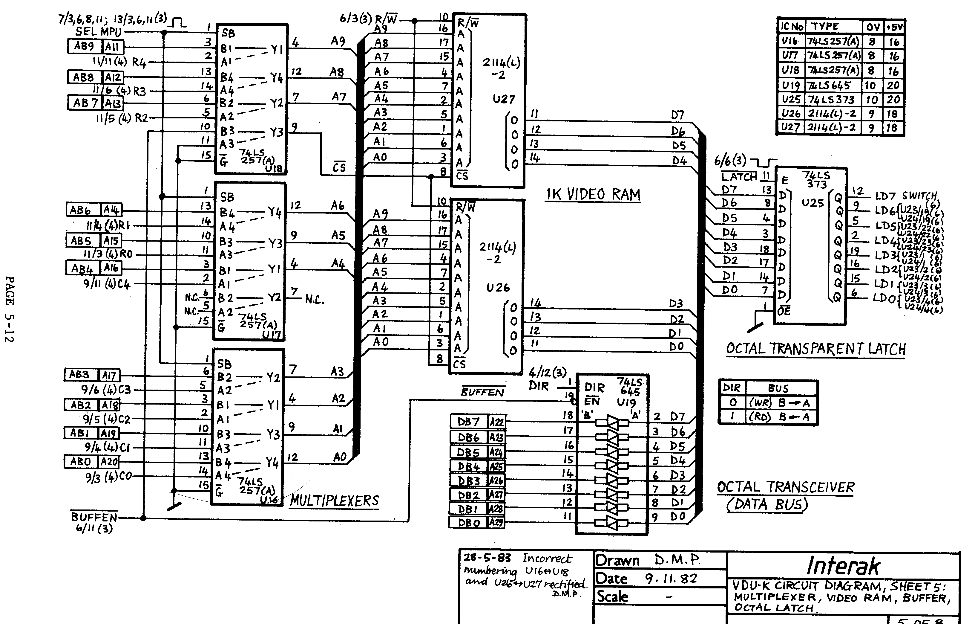
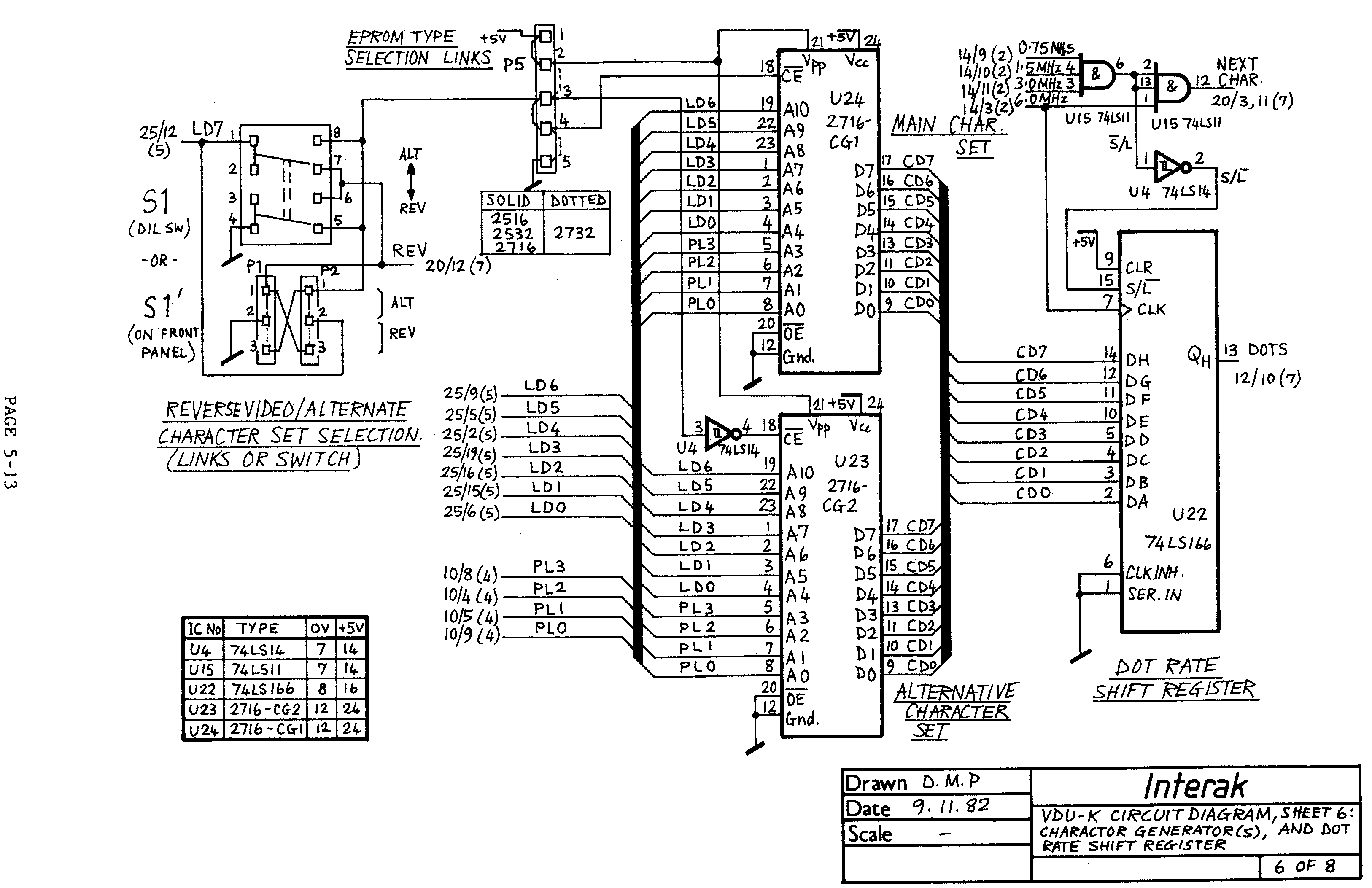
5.4 Circuit Diagrams 5-8, 5-9, 5-10, 5-11, 5-12, 5-13, 5-14, 5-15
5.5 Component Overlay Diagram 5-16
(Total no. of pages Issue 2: 90)
PAGE 1-3
October 1982: Issue 1.1
May 1983: Issue 1.2
PAGE 1-4
Some of the Integrated Circuits used on this card are supplied packed in special anti-static packing (tubes, foil, or foam), and have a warning notice affixed to the packing.
Do not be alarmed, experience shows that damage due to mis-handling very rarely happens. The damage is due to static electric charges, being transferred from an object or person through the leads of the integrated circuit to the tiny chip inside. Only some types of IC are vulnerable, e.g. MOS or CMOS types, and some of the latest shallow diffusion high-speed bipolar types.
The initials MOS stand for "Metal-Oxide-Semiconductor". The oxide is, for example silicon dioxide - an excellent insulator, which insulates the metal from the silicon.
However the scale of IC chip manufacture is so small that the layer of oxide is easily damaged by excessive static charges which "punch through" the insulating layer.
Sometimes the damage is not immediately noticed (which might explain how some people disregard all precautions and appear to get away with it), but during the months and years which follow, metal "ions" can migrate through the hole and failure can eventually result.
We would liken the risk of causing this damage to the risk of getting caught "speeding" in a motor car. Of course there are people who disregard all speed limits and never get caught, just as there are people who disregard handling precautions with no adverse effects. But do remember, every so often you meet someone who has been disqualified from driving due to speeding, so do not let him handle your ICs!
The full set of handling precautions is given on the next page; as mentioned, not everybody follows them all to the letter, but at least you cannot say you haven't been warned!
PAGE 1-5
Before unwinding any wire shorting together the pins of the ICs, or removing the ICs from their protecting metal or anti-static carrier tube, container, or anti-static foam, please read the following precautions:
PAGE 1-6
PAGE 1-7