VDU-K Interak 1
VDU Interface Section 4: Appendices
4.1 Appendix 1: Standard Character Set
Ref. CG02.XX
This characters shown on this page and the page following are
an example of one set of characters that has been defined as a
standard character generator set. They are largely based on the
printable ASCII characters, but characters have also been
allocated to the non-printable codes, such as carriage return,
line feed, etc. Some further points to note are given at the end
of the table on the next page. Purchasers of the VDU-K card as a
"bare board" can obtain a pre-programmed character
generator EPROM from their supplier at modest cost.
| Hex. |
ASCII |
Displays |
Hex. ASCII Displays |
Hex. |
ASCII |
Displays |
Hex. |
ASCII |
Displays |
00
01
02
03
04
05
06
07
|
NUL
SOH
STX
ETX
EOT
ENQ
ACK
BEL
|
¿ Graphics Space
¿ Block Graphics
¿ Block Graphics
¿ Block Graphics
¿ Block Graphics
¿ Block Graphics
¿ Block Graphics
¿ Block Graphics
|
20 SP ASCII Space
21 !	!
22 "	"
23
24 $ $
25
26 & &
27
|
40
41
42
43
44
45
46
47
|
SP
A
B
C
D
E
F
G
|
A
B
C
D
E
F
G
|
60
61
62
63
64
65
66
67
|
a
b
c
d
e
f
g
|
a
b
c
d
e
f
g
|
08
09
0A
0B
0C
0D
0E
0F
|
BS
HT
LF
VT
FF
CR
SO
SI
|
¿ Graphics Space
¿ Block Graphics
¿ Block Graphics
¿ Block Graphics
¿ Block Graphics
¿ Block Graphics
¿ Block Graphics
¿ Block Graphics
|
28
29
2A * *
2B + +
2C
2D
2E
2F
|
48
49
4A
4B
4C
4D
4E
4F
|
H
I
J
K
L
M
N
0
|
H
I
J
K
L
M
N
0
|
68
69
6A
6B
6C
6D
6E
6F
|
h
i
j
k
l
m
n
o
|
h
i
j
k
l
m
n
o
|
10
11
12
13
14
15
16
17
|
DLE
DC1
DC2
DC3
DC4
NAK
SYN
ETB
|
¿ Line Drawing Char.
¿ Line Drawing Char.
¿ Line Drawing Char.
¿ Line Drawing Char.
¿ Line Drawing Char.
¿ Line Drawing Char.
¿ Line Drawing Char.
¿ Line Drawing Char.
|
30 0 0
31 1 1
32 2 2
33 3 3
34 4 4
35 5 5
36 6 6
37 7 7
|
50
51
52
53
54
55
56
57
|
P
Q
R
S
T
U
V
W
|
P
Q
R
S
T
U
V
W
|
70
71
72
73
74
75
76
77
|
p
q
r
s
t
u
v
w
|
p
q
r
s
t
u
v
w
|
18
19
1A
1B
1C
1D
1E
1F
|
CAN
EM
SUB
ESC
FS
GS
RS
US
|
¿ Line Drawing Char.
¿ Line Drawing Char.
¿ Line Drawing Char.
¿ Alien 0
¿ Alien 1
¿ Alien 2
¿ Vehicle L.H.
¿ Vehicle R.H.
|
38 8 8
39 9 9
3A
3B
3C
3D
3E
3F ?	?
|
58
59
5A
5B
5C
5D
5E
5F
|
X
Y
Z
[

]
|
X
Y
Z
[

]
|
78
79
7A
7B
7C
7D
7E
7F
|
x
y
z
{

}

DEL
|
x
y
z
{

}

DEL
|
Some points to note on the tables above and the previous page:
The characters for 00 and 20 both display as a blank space; 00
can be used as a "graphics" space, and 20 can be used
as an "alphanumerics" space. The character for code 5F
(ASCII back arrow) displays as the underline character
"_". The character for code 60 (ASCII \) displays as
"6", code 7C (|) displays as "÷", and code
7F (DEL),displays as a chequerboard pattern (alternating black
and white dots). These changes are to comply with convention in
some cases, and special requests in others.
Note that if the reverse video option is selected there are a
further 128 characters which are simply the reverse video
versions of those listed. Their code is found by adding hex. 80
to the codes listed, so for example 2A is the "*"
character, AA (=80+2A) is the same in reverse video.
4.2 Appendix 2: Character Generator
EPROM
Section 4.1 of this Manual has given an example of one set of
characters for what might be termed a standard character set,
which is likely to be adopted by most users of the VDU-K. (A
programmed EPROM can be obtained at modest cost by VDU-K
purchasers from the supplier of the VDU-K card.)
However, many users may wish to make minor detail changes to
the characters, or of course may wish to devise their own, this
being one of the main attractions of the card. (It is often a
great benefit to be able to have a preprogrammed set of special
characters, since this saves the software overhead suffered by
ostensibly more sophisticated systems which have a RAM based set,
and thus have to burden the main program with the task of storing
the required character set within itself.)
The arrangement of the various data within the character
generator EPROM has not been decided lightly. As each bit set to
a "1" in the EPROM corresponds to a lighted dot in the
finished character (displayed in normal, not reversed, video), it
might not be thought important which particular addresses are
used, as long as they are defined. The arrangement which has been
adopted in the VDU-K design has been carefully chosen to make the
design and programming of a custom set of
"applications" characters as easy as possible.
For example the first byte of the data to compose the
character "A" (ASCII code 41H, the "H” suffix
meaning hexadecimal notation) is to be found at the EPROM address
410H, i.e. 41H x 10H, similarly the data for code 62H (ASCII
letter "b"), are found at addresses beginning 620H.
As each character cell is eight dots wide, an eight bit byte
is ideally suited to the purpose of storing the pattern of dots.
The convention used in this design is that the most significant
bit is the one which appears at the left-hand side of the
character cell, and the least significant bit is the one on the
right. This makes it quite easy to visualise characters, since if
the byte is written out in binary format the 1's will represent
lit dots, and the 0’s will represent blank dots. It is
perhaps even easier to imagine the appearance of the displayed
character if say "*" is used for a "1", and
"-" for a "0”.
For example if the contents of 410H in the EPROM were 0FH
(actually in the standard character generator they aren't, but
say they were), then the top line of the character coded 41H
would appear as:
----**** (since 0FH = 00001111)
if they were F0H the top line would be
****---- (since F0H = 11110000)
Similarly for the following data:
Address Data  Display  Binary
(Hex.)
410     00    -------- 00000000
411     10    ---*---- 00010000
412     28    --*-*--- 00101000
413     44    -*---*-- 01000100
414     44    -*---*-- 01000100
415     7C    -*****-- 01111100
416     44    -*---*-- 01000100
417     44    -*---*-- 01000100
418     00    -------- 00000000
419     00    -------- 00000000
The example above this time is the actual sequence of ten
consecutive bytes which are found in the standard character
generator EPROM starting at address 410H, and it may be seen that
it represents the letter "A", ASCII code 41H.
Ten consecutive bytes are used to make up the character cell,
which is a 8 x 10 matrix of dots. The alphanumeric characters do
not extend to the sides of the cell in all directions, as for
good legibility a blank space is required between adjacent
characters, horizontally, and vertically.
The convention which has been followed in the standard
character generator EPROM is to compose all the upper-case
(capital) letters on a 5 x 7 matrix, located within the 8 x 10
cell as shown in the example above. For each of the alphanumeric
characters the top row of dots in the cell is blank, as is the
left column and the two right columns. The lower-case letters are
mostly composed on a 5 x 5 matrix which begins two rows lower
than the tops of the upper-case letters. Some of the lower-case
letters e.g. g, j, p, etc. have "descenders", i.e. the
character has parts which are lower than the bottom row of the
upper-case letters. Lower-case letters with descenders are
composed on a 5 x 7 matrix like the upper-case letters, but
displaced downwards by two rows.
If it is required that adjacent characters "join up"
then no blank rows or columns should be left. An example of one
such character in the standard character generator EPROM is given
below; it is the "pixel" character 09H, which is
located in the EPROM at address 090H:
Address Data Display  Binary
(Hex.)
090     F0   ****---- 11110000
091     F0   ****---- 11110000
092     F0   ****---- 11110000
093     F0   ****---- 11110000
094     F0   ****---- 11110000
095     0F   ----**** 00001111
096     0F   ----**** 00001111
097     0F   ----**** 00001111
098     0F   ----**** 00001111
099     0F   ----**** 00001111
It should be noted that the size of the character cell
displayed on the standard VDU-K card is very close to being
square. This is of arguable benefit in the case of alphanumeric
characters, but it makes the design of graphic displays
particularly easy.
The amount of space in the EPROM devoted to each character is,
as discussed above, ten consecutive bytes. There are in fact
sixteen successive bytes available in the EPROM for each
character but the last six are not displayed. They can be any
code, for example "FFH", the natural state of an
unprogrammed EPR0M, or "00H", the code for blank dots,
or indeed anything, as these end groups of six bytes are not
displayed.
For certain special applications of the VDU-K, some users may
substitute a binary counter type 74LS293 for U10 in place of the
normal decade counter type 74LS290, since these two devices are
pin compatible. If this is done the screen display can no longer
be 24 rows of characters, about 16 rows will be the usable
maximum, this being a consequence of the fact that each character
cell will be increased to display a 8 x 16 matrix of dots. In
this case sixteen successive locations in the character generator
EPROM will be used for each character instead of the previous 10,
plus 6 spare.
Procedure for the Design of Custom
"Applications" Characters.
If the application involves a repeating set, such as say a set
of chess men then the design of each individual character should
be carried out on graph paper. A chess men EPROM has already been
designed, and it proved very convenient to make each piece occupy
a matrix of 16 x 20 dots, i.e. four character cells, two
horizontally, two vertically. Other applications may be best
satisfied by a different arrangement of character cells, e.g.
representations of say sheep, pigs, and cows (for say
kindergarten use, teaching children to read, or perhaps for some
serious use down on the farm), could be made in a matrix of say
32 x 20, i.e. eight character cells each, four horizontally, two
vertically.
Once the shape and format has been designed the various dots
can be divided into their eight bit bytes, and programmed into
the Applications EPROM at convenient locations.
An alternative type of screen display is one which is not
repetitive. An example of this would be a representation of a
section of the British Isles for say Meteorological use in
preparing a weather map. In such an application there would be
fixed features, and repetitive ones (e.g. sun and cloud symbols).
At first sight there might be thought to be insufficient
character cells available, since at least one is needed for each
section of coastline. This latter statement is true, but there
will still be plenty of characters left over when it is realised
that the British Isles is mostly land, surrounded by mostly sea.
Although the sea for example might take the greatest area on the
screen it could possibly be represented by just a single
"sea" character (ASCII code "43" perhaps, ho
ho), leaving plenty for the other details.
As before graph paper should be used to design the screen
layout, but before the EPROM is programmed it should be decided
what character codes will be used in the area of interest. For
totally patternless areas such as geographical displays, it might
be most convenient just to fill that area of screen with
ascending character codes, e.g. 80H, 81H, 82H, 83H, etc., and
program the features required into the appropriate codes, using
perhaps a co-ordinate system. Once written the character codes in
the video RAM would not change, unless it was desired to replace
for example a piece of Wales with a piece of Scotland.
4.3 Appendix 3: Timing Generator EPROM
The TV sync. pulses and other timing pulses are produced by
the on-board Z80A-CPU, running a program which is one of those
contained in the timing generator EPROM U2. The programs are very
simple in concept, but quite complicated in execution.
In this Section of the Manual only an indication of the
methods used will be given, for two purposes:
Firstly so that the interested user can say with confidence
that he knows the precise purpose of every component part of his
Interak 1 System, and secondly to give a certain amount of
guidance to those users who are wishing to use the technique to
construct their own timing EPROM for some special modification to
the VDU-K card, or perhaps even some similar design of their own.
The Z80A-CPU and the EPROM together make one of the very
smallest computer systems imaginable. No external RAM is used as
the CPU chip itself contains sufficient for the purpose. The
principle of operation is very simple and consists of writing
chosen data to a storage latch. The outputs of the latch are the
required timing signals. In essence, if a "1" is
written to a "bit" of the latch its output goes high,
and stays high until a "0" is written, at which point
it goes low. Since the clock input to the CPU is crystal
controlled, the signals obtained from the outputs of the latch
are very precisely controlled, and are absolutely stable, and
repeatable from VDU-K card to VDU-K card.
The various time intervals required for a TV sync. pulse
generator are made up from such short intervals as 2.33
microseconds. (See Section 5.2 of this manual for the Timing
Diagrams). Intractable figures such as this become fairly easy to
work with when a 3.0 MHz clock is used for the CPU: With a 3.0
MHz clock 2.33 microseconds is 7 "T" states (a
"T" state being the smallest unit of time considered in
the operating cycle of a Z80A microprocessor and is the lencth of
time for one cycle of the clock). Reference to the precise time
of the instructions available in the Z80A's repertoire shows that
many of them (e.g. LD (HL),A) are exactly 7 "T" states
long. The length of a whole TV line (64 microseconds) is a whole
number of ”T" states (actually 192), and similarly the
time duration for the visible part of the display (42.66
microseconds) is exactly 128 "T" states long.
It should be stressed that when time delays as little as 7
"T" states are required such circuits as a Z80A-CTC
(Counter Timer Circuit) provide no benefit. Even with the
Z80A-CPU's fast interrupt response the time taken would be much
too long, to say nothing of the fact that the extra chips
required would remove the outstanding benefit of low cost and
small chip count. It is for similar reasons that some of the
counting which could have been done in software has in fact been
carried out by hardware (e g. the cost of two four bit counters
in the shape of a 74LS393 is not so very different to that of an
eight bit latch, especially when extra decoding is added to
enable the latch, and as a bonus the hardware counter occupies
less board space).
In this design the only thing which is read by the CPU is the
EPROM, and the only thing which is written to is the latch, and
so there is no need for any decoding or differentiation between
I/O space and Memory space; the !RD (read) line from the CPU
enables the EPROM directly, and the !WR (write) line clocks the
latch.
Although the VDU-K card requires only four timing lines (shown
on the diagram as V, H, R, S), a six bit latch has been provided
to allow for unspecified future applications (for example to
provide separate line and frame sync. pulses for TV monitors
which cannot accept both line and frame sync. combined).
A novice might be concerned that the action of changing the
output of one of the timing lines might disturb one of the
others, since all bits in the latch are written to at the same
time. There is no need to worry about this as there is in fact no
problem. The secret is to remember that if a line is to remain
unchanged at a particular point in the timing cycle, it is
perfectly acceptable to write data to the appropriate
"bits" of the latch, provided they include the same
data for those "bits", i.e. continuously writing
"1's" on top of "1’s" will result in
constant unchanging "1‘s" as outputs, and
similarly for "0's" written repeatedly on top of
"0's".
In the case of a non-interlaced display each consecutive TV
frame has 312 picture lines, and the control program continuously
loops round a sequence of instructions which take 312 x 64
microseconds to complete, i.e. 59,904 "T" states, no
more, no less. An interlaced display has a sequence which is
exactly 625 lines long (ideally suited to a 625-line TV set),
i.e. exactly 120,000 "T" states. This latter sequence
is divided into two consecutive TV frames, one having 312 picture
lines, and the next having 313 (312 + 313 = 625). In the case of
an interlaced display the commencement of the frame sync pulse
alternates between starting at the beginning of a TV line, and
half way through it. The effect of this on the TV screen is to
cause adjacent frames of an interlaced display to have lines
which are displaced by half the distance between them. This gives
a superior display for TV broadcast pictures viewed from a
distance of several metres, but the technique is of dubious
benefit when computer pictures are viewed close-up. So that all
schools of thought may be accommodated, the standard timing
generator EPROM supplied includes programs for each format.
There are some diagrams in Section 5.2 of this Manual which
illustrate the description in the previous paragraph, but as the
authors of the manual prefer to think of themselves as computer
boffins rather than TV boffins, the reader is referred to any
book on the principles of television for a fuller and more lucid
description.
It is hoped that a full listing of the program will be made
available for an appropriate fee, in order to aid any users who
wish to write their own, or modify that provided. Such a listing
does not exist at the time of writing, since much of the required
timing was derived empirically. Part of the reasons for this will
be appreciated if the following caution is understood:
Any users who are writing their own timing program should not
fall into the trap of thinking that a given output will persist
for the duration of the instruction which caused it. For example
it might be thought that an instruction 7 "T" states in
long which writes a "1" to the output latch (assumed to
be previously "0"), followed by an instruction 10
"T" states long which writes a "0", would
result in a positive pulse of duration 7 "T" states.
This is not normally the case; in the example above the pulse
would have a duration nearer the 10 "T" state mark. The
reason for this is that the effect of a write instruction only
occurs towards the end of that instruction, the early part being
taken up with the op-code fetch, the refresh cycle, and so on. In
other words, for the majority of the 7 "T” state
instruction above the output was "0", and remains
"0". It goes to "1", somewhere near the end,
and then remains at "1" for most of the 10
"T" state instruction which follows it. After about 10
"T" states the instruction takes effect and the
"1" output returns to "0". To summarise, in
this example a 7 "T" state instruction to produce a
positive pulse results in a pulse which in fact turns out to be
10 "T" states long.
It can be appreciated that the task of writing a program which
depends for its operation on precise selection of instructions
having the desired number of "T" states, is a task
which is made doubly difficult when the timing must be taken not
from the instruction under consideration, but from the
instruction which follows it.
The diagrams in Section 5.2 illustrate on example of the
results of such labour. The program to produce the desired
waveforms is at first extremely difficult to understand because
it follows none of the normal logical rules of programming; most
of the instructions are concerned solely with filling in time
(counted out with meticulous accuracy to the individual
"T" state). When the time comes for a decision in the
program, for example after 240 visible picture lines have been
displayed, and it is time to move into the blank bottom margin,
then normal relative conditional jumps cannot be employed, since
they take a different number of "T" states according to
whether or not the condition has been met. In the same way care
has to be taken at the point when the whole program loops back to
begin again, to ensure that an extra 10 "T" states are
not inserted inadvertently into one of the final picture lines
when the jump is made. In the case of the very tiny time interval
2.66 microseconds (i.e. 7 "T" states) the time taken by
an absolute conditional jump (10 "T" states) is too
long. This happens when the five "half-line equalisation
pulses" are to be generated, and it proves expedient to
produce these five pulses by writing the code out five times in a
row rather than to set up a loop counter, which would be the
conventional way in a "normal" program.
Even with this necessary wastefulness of memory space the
program to do the whole job occupies only about 0.5K, and there
is space for four such programs in the standard type 2716 EPROM.
Two of the four programs are switch selectable, and are generally
the same format, but for interlaced and non-interlaced displays.
The other two are link-selectable (by breaking a small piece of
track), and could be some other format, for example a 16-line
display instead of 24-lines, or perhaps to suit a 525-line 60Hz
TV set instead of the usual 625-line 50 Hz type.
4.4 Appendix 4: VDU RAM Memory Map for
Interak 1.
There are 32 x 24 = 768 locations on the VDU screen, each of
which corresponds to a unique memory location in the memory map
of the computer. The actual addresses will of course depend on
the settings of the switches S2a-f, which are under the control
of the user of the VDU. However, if they are set to suit ZYMON 2
(i.e. S2a-f ’on', with S2g-h "off"), then the
address of the top left-hand corner of the VDU will be F000H, and
the addresses will follow consecutively until the bottom
right-hand corner of the VDU is reached at address F2FFH.
The table which follows gives the start and end addresses for
each row of characters which can be displayed on the VDU screen
(the addresses are given in hexadecimal notation, the
"H" suffix being omitted to make them a little easier
to read).
| Row |
|
0 ... 32 Columns ... 31 |
|
| 0 |
F000 |
|
|
|
|
|
|
|
|
|
|
|
|
|
|
|
|
|
|
|
|
|
|
|
|
|
|
|
|
|
|
|
|
F01F |
| 1 |
F020 |
|
|
|
|
|
|
|
|
|
|
|
|
|
|
|
|
|
|
|
|
|
|
|
|
|
|
|
|
|
|
|
|
F03F |
| 2 |
F040 |
|
|
|
|
|
|
|
|
|
|
|
|
|
|
|
|
|
|
|
|
|
|
|
|
|
|
|
|
|
|
|
|
F05F |
| 3 |
F060 |
|
|
|
|
|
|
|
|
|
|
|
|
|
|
|
|
|
|
|
|
|
|
|
|
|
|
|
|
|
|
|
|
F07F |
| 4 |
F080 |
|
|
|
|
|
|
|
|
|
|
|
|
|
|
|
|
|
|
|
|
|
|
|
|
|
|
|
|
|
|
|
|
F09F |
| 5 |
F0A0 |
|
|
|
|
|
|
|
|
|
|
|
|
|
|
|
|
|
|
|
|
|
|
|
|
|
|
|
|
|
|
|
|
F0BF |
| 6 |
F0C0 |
|
|
|
|
|
|
|
|
|
|
|
|
|
|
|
|
|
|
|
|
|
|
|
|
|
|
|
|
|
|
|
|
F0DF |
| 7 |
F0E0 |
|
|
|
|
|
|
|
|
|
|
|
|
|
|
|
|
|
|
|
|
|
|
|
|
|
|
|
|
|
|
|
|
F0FF |
| 8 |
F100 |
|
|
|
|
|
|
|
|
|
|
|
|
|
|
|
|
|
|
|
|
|
|
|
|
|
|
|
|
|
|
|
|
F11F |
| 9 |
F120 |
|
|
|
|
|
|
|
|
|
|
|
|
|
|
|
|
|
|
|
|
|
|
|
|
|
|
|
|
|
|
|
|
F13F |
| 10 |
F140 |
|
|
|
|
|
|
|
|
|
|
|
|
|
|
|
|
|
|
|
|
|
|
|
|
|
|
|
|
|
|
|
|
F15F |
| 11 |
F160 |
|
|
|
|
|
|
|
|
|
|
|
|
|
|
|
|
|
|
|
|
|
|
|
|
|
|
|
|
|
|
|
|
F17F |
| 12 |
F180 |
|
|
|
|
|
|
|
|
|
|
|
|
|
|
|
|
|
|
|
|
|
|
|
|
|
|
|
|
|
|
|
|
F19F |
| 13 |
F1A0 |
|
|
|
|
|
|
|
|
|
|
|
|
|
|
|
|
|
|
|
|
|
|
|
|
|
|
|
|
|
|
|
|
F1BF |
| 14 |
F1C0 |
|
|
|
|
|
|
|
|
|
|
|
|
|
|
|
|
|
|
|
|
|
|
|
|
|
|
|
|
|
|
|
|
F1DF |
| 15 |
F1E0 |
|
|
|
|
|
|
|
|
|
|
|
|
|
|
|
|
|
|
|
|
|
|
|
|
|
|
|
|
|
|
|
|
F1FF |
| 16 |
F200 |
|
|
|
|
|
|
|
|
|
|
|
|
|
|
|
|
|
|
|
|
|
|
|
|
|
|
|
|
|
|
|
|
F21F |
| 17 |
F220 |
|
|
|
|
|
|
|
|
|
|
|
|
|
|
|
|
|
|
|
|
|
|
|
|
|
|
|
|
|
|
|
|
F23F |
| 18 |
F240 |
|
|
|
|
|
|
|
|
|
|
|
|
|
|
|
|
|
|
|
|
|
|
|
|
|
|
|
|
|
|
|
|
F25F |
| 19 |
F260 |
|
|
|
|
|
|
|
|
|
|
|
|
|
|
|
|
|
|
|
|
|
|
|
|
|
|
|
|
|
|
|
|
F27F |
| 20 |
F280 |
|
|
|
|
|
|
|
|
|
|
|
|
|
|
|
|
|
|
|
|
|
|
|
|
|
|
|
|
|
|
|
|
F29F |
| 21 |
F2A0 |
|
|
|
|
|
|
|
|
|
|
|
|
|
|
|
|
|
|
|
|
|
|
|
|
|
|
|
|
|
|
|
|
F2BF |
| 22 |
F2C0 |
|
|
|
|
|
|
|
|
|
|
|
|
|
|
|
|
|
|
|
|
|
|
|
|
|
|
|
|
|
|
|
|
F2DF |
| 23 |
F2E0 |
|
|
|
|
|
|
|
|
|
|
|
|
|
|
|
|
|
|
|
|
|
|
|
|
|
|
|
|
|
|
|
|
F2FF |
The purpose of providing the above table is to give a guide
for users who are designing a screen display, and therefore need
to know where each line of characters begins and ends.
4.5 Appendix 5:
Interlaced/Non-Interlaced Display
The difference between an interlaced and non-interlaced
display has been mentioned at appropriate places in this manual,
in the general description, the detailed description, switch
settings, timing generator EPROM description, and so on. In each
section the subject of interlaced and non-interlaced display has
been approached from the point of view of the needs of the user
at the time he is reading that section of the manual.
In this appendix the subject is covered again simply to
provide a handy reference point, to save the casual reader from
having to wade through the whole manual to find the information.
Commonly the type of TV receiver for which the VDU-K is
designed is described as "625-line". There are not many
people who have tried to count the number of lines on a TV
picture and have remained sane, but those who have will be able
to confirm that not all are displayed; there are a number
missing.
The missing lines occur at the end of the picture when the
electron beam which forms the picture is returning to the top of
the screen. They are blanked in the TV receiver, because they
would spoil the display as they spot is travelling upwards much
faster than it travelled down. The blanked lines are known as
"frame flyback" lines, and they are only visible on
badly adjusted TV receivers.
Thus there are less than 625 lines displayed on a 625 line TV
receiver. In fact the 625 lines mentioned above are achieved by
an illusion, only present in an "interlaced" display.
In an interlaced display consecutive "frames" are
alternately "odd" and "even". (A
"frame" is a complete scan of the whole screen, which
takes place in 20 milliseconds, i.e. one fiftieth of a second, as
there are fifty frames displayed per second.) Since there are two
types of frame, "odd" and "even" it can be
seen that there are twenty-five of each type to make up the total
of fifty. Including the blank lines, there are 312.5 lines to
each frame in an interlaced display. The consecutive odd and even
frames are displaced vertically by one half the distance of
separation of adjacent lines by an ingenious method of timing the
frame synchronisation pulse, and due to the effect known as
"persistence of vision" the viewer sees both sets
simultaneously (excluding of course the invisible blanked lines)
and thus observes 312.5 + 312.5 = 625 lines, Q.E.D.
The ingenious method referred to above was devised by the
television engineers of long ago and is to arrange that the frame
flyback starts half way along the the last line of an odd field,
and at the end of the last line of an even field. Successive
fields therefore start at a time which is different to the
preceding field to the extent of half a line, which results in a
vertical difference of one half the spacing of adjacent scan
lines.
At the end of this section of the manual there is a diagram
which attempts to clarify the above description, and demonstrate
visually the difference between an interlaced and a
non-interlaced TV display.
It will be seen in the case of the interlaced display that the
number of lines displayed for each frame is a whole number, which
may seem to conflict with the description above referring to a
fractional number (312.5). This is fairly easily resolved when it
is appreciated that the time taken for the frame flyback includes
the missing half line.
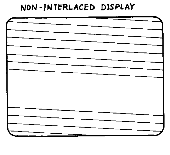
By comparison, the non-interlaced display is quite simple. In
a non-interlaced display all fields are the same
"hybrid" type i.e. they start as "odd" fields
and finish as "even". The extra half line which was
used to cause the alternation of frames to give the interlaced
display is removed, and each frame consists of 312 lines.
Consequently the time taken to complete fifty frames is reduced
slightly, and the frame frequency is thus increased from 50.00 Hz
to 50.08 Hz. This is entirely insignificant in this application.
(It would however be important if the signals from this card were
being blended into an existing TV display, e.g. to insert
subtitles etc. into a broadcast TV picture. In such a case the
12.0 MHz master crystal would have to be reduced in frequency
slightly, or perhaps more practically, the interlaced option of
the timing generator should be chosen for this application
instead of non-interlaced )
Ostensibly the interlaced format is the superior one, and
indeed it is for moving conventional broadcast TV pictures.
Viewed from a few metres away the scan lines can hardly be seen.
However things are a little different for close-up viewing of
computer style material. Many people report a disturbing flicker
which makes the interlaced display less than ideal for viewing
for a long time. The probable reason is that each of the two
types of frame ("odd” and "even") in an
interlaced display is only repeated every other frame, i.e.
twenty five times per second. This frequency is low enough to
cause visible flicker, particularly when, as is the case in a
typical computer display, there are only sharp changes from white
to black, rather than hazy changes of intensity from white via
grey to black.
When this point is considered it can be sean that there is a
chance that a non-interlaced display may prove to be without the
disadvantages mentioned above. As the same frame is repeated
fifty times a second rather than the twenty five times a second,
which is the case when the "even" frame is interlaced
with the "odd" one, the resulting picture is much
steadier, and in most cases is preferred by users who spend a lot
of time close up to their screen.
If special computer display monitors with long-persistence
phosphors are used then the effect of flicker is much less
pronounced and the interlaced display might give subjectively
superior results. (Note that although long persistence phosphors
are often green, the reverse is not true. Green screens on TV
monitors are most often not long-persistence types. This could
have a lot to do with the description "TV monitor"; if
a monitor is actually to be used for TV pictures, it cannot
really have a long persistence screen, because if it did it would
give a most unacceptable "smearing" of quick movement
in pictures on the screen )
Interlaced Display
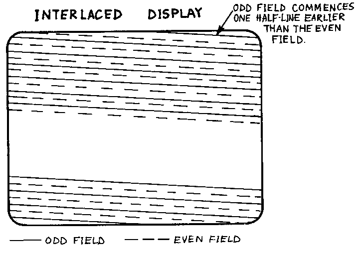
Odd field commences one half-line earlier than the even
field.
______Odd field - - - - Even Field |
Non-Interlaced Display
 |
| The 312.5
lines in the odd field are 'interlaced' with the 312.5
lines in the even field to form the conventional 625-line
TV display (312.5 + 312.5 = 625). Not all the lines are
visible, and the half-line in each frame is absorbed
during the frame flyback time, which is not a whole
number of lines. Note that the original picture
elements are refreshed only in alternate frames, hence a
long-persistence phosphor is needed to avoid flicker when
the screen is viewed close up. However a long persistence
phosphor will cause 'smearing' if the picture includes
any animated elements, so some trade-offs are involved in
interlaced displays.
|
A 'hybrid'
field (starts 'odd', finishes 'even'), is repeated in
every consecutive frame. Individual picture elements are
therefore refreshed in every frame, i.e. twice as often
as in the interlaced display. In many cases a steadier,
more pleasing picture is the result, particularly on a
screen with a short-persistence phosphor (e.g. a video monitor,
with or without green screen, or a domestic TV receiver).
|
Drawn: DMP
Date: 1982-11-09 |
4.6 Appendix 6. Effect of A.C. Coupling
in Video Circuits.
At the end of this Section is a <diagram which illustrates
the effect. It is a symbolic diagram rather than an actual
picture of a video waveform, and it shows the effect of a.c.
coupling in video circuits. In general, the effect of a.c.
coupling is detrimental, and for this reason the video output
from the VDU-K card is not connected via a coupling capacitor.
From the diagram it can be seen that the average (sometimes
called the "d.c.") level of a video signal which is
a.c. coupled will depend quite markedly on the picture content,
(This effect is due to a property of a.c. coupled circuits, and
any text-book on basic a.c. theory will provide further
explanation should the reader require it.) If there is a lot of
white in the picture, the average level will sink down, and it
will rise again if the picture contains a lot of black instead of
white. The TV receiver or monitor will have contrast and
brilliance controls which will permit a good picture to obtained
for one or other of these extremes but not both. The diagram
shows that if a setting is found which is right for one condition
it will not be right for the other.
This subject is raised here simply so that the user who finds
this trouble will mislead himself into thinking there is
something wrong with his VDU-K card; the "fault" is in
the TV or monitor.
The effect will be demonstrated most clearly if the TV or
monitor controls are adjusted for a picture which is
predominantly black, with just one or two words displayed
normally. If a program is then run which turns most of the screen
white (e.g. a program which writes a lot of inverse video
characters on the screen), then it is often the case that the
orignal (normal video) characters will become almost illegible
until the brilliance and contrast controls are adjusted on the TV
monitor. This is due to the shift in average level in the video
signal, which is demonstated on the diagram.
It is generally not possible to d.c. couple the video
throughout in the TV receiver or monitor because of the difficult
circuit design problems this would cause, however a top-quality
TV receiver or video monitor will have a few extra components
added in its circuit to provide a feature known as
"black-level clamp". With this feature the undesirable
effect of a.c. coupling the video signal will be removed, as the
black level clamp forces the black level (and thus the white
level) to be held at a fixed potential, so that it does not
change with picture content.
Almost all TV receivers are built on a very low budget and
their designers cannot justify the luxury of "black level
clamping”. Partly the reason is to do with the demands this
would place on the regulation of the set's EHT (Extra High
Tension, i.e. high voltage) supply. As a.c. coupling in the video
circuits results in an all black screen being lightened to grey,
and/or an all white screen being darkened, there is far less
change than there would otherwise be in the demands made on the
EHT supply (which would otherwise be very low for a black
screen and very high for a white screen). The very poor EHT
regulation on some sets is very visible on those which change the
size of the picture according to the intensity of the picture
being transmitted.
It might be thought that a video monitor would not suffer
these defects being built to far more stringent standards (and
thus costing a lot more into the bargain!). However nowadays most
so-called monitors are nothing more than TV receiver designs
simply with the aerial and tuning circuitry stripped out and a
green phosphor screen fitted, and so they inherit the
deficiencies of the TV receivers from which they are derived.
There is little that can be done to improve matters if the
described effect causes any inconvenience; even if the minor
circuit changes required to provide "black level clamp"
can be devised, they should not be undertaken lightly since they
may result in an intolerable burden being placed on the
insulation and general construction of the EHT supply if its
voltage is caused to rise significantly.
As stated before in this manual, the authors do not feel
highly qualified as teachers when it comes to discussing matters
of this kind, and so the reader is directed to seek guidance from
a any suitable reference book on the subject of television
receiver and TV monitor design and kindred matters.