CONTENTS Page
Technical Specification            2
Safety Tests                       2
Self-Test Activitation             3
Cabinet Drawing & Parts List     4&5
Flow Charts                      6-9
PCB                          10 & 11
Disk Drive Diagrams         12,13,14
Software Errors                   15
Diagnostic Flow Chart             16
Self Diagnostic Tests             17
Circuit Diagram              18 & 19
Electrical Parts List             20
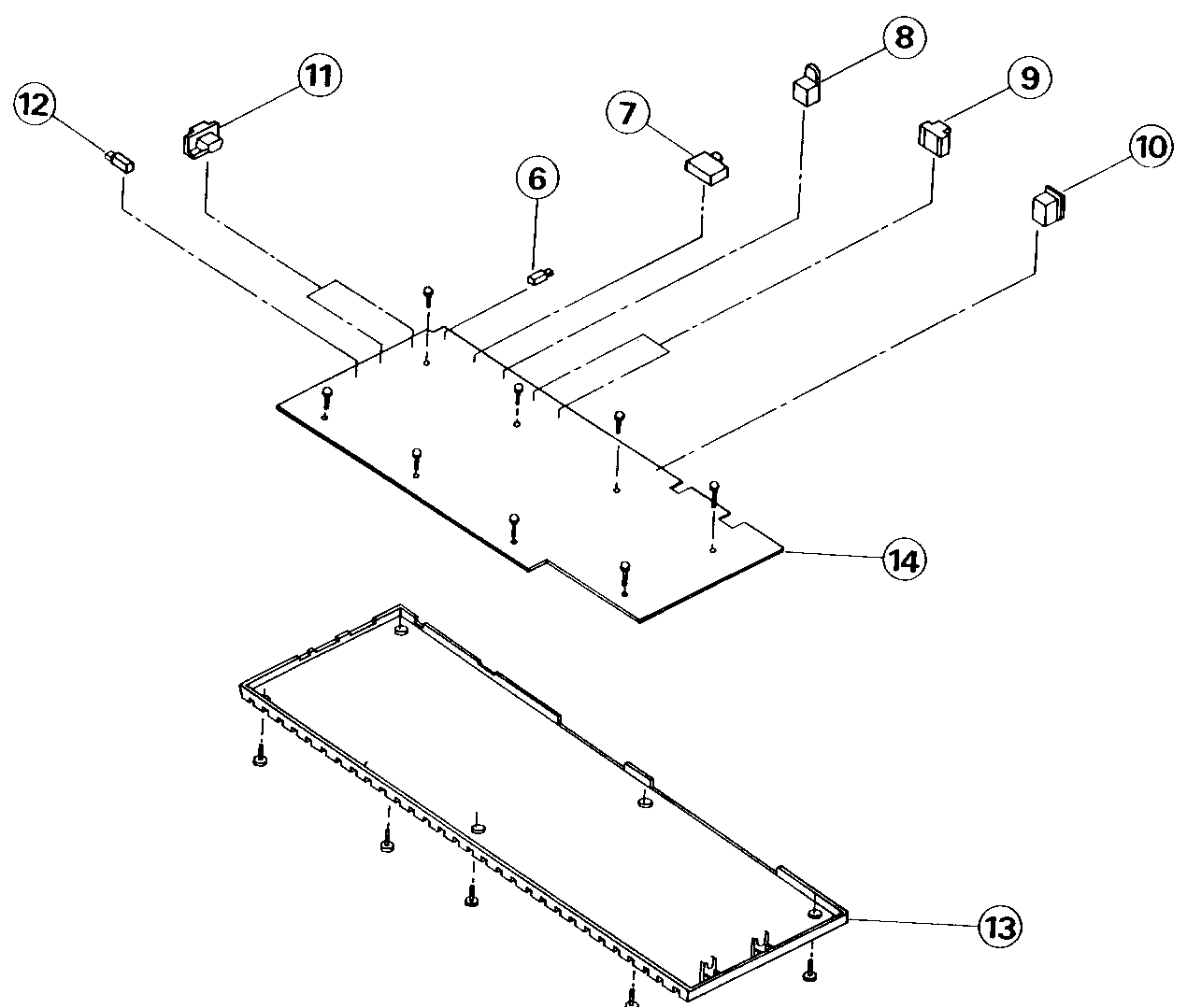
| Ref | Description | Part number |
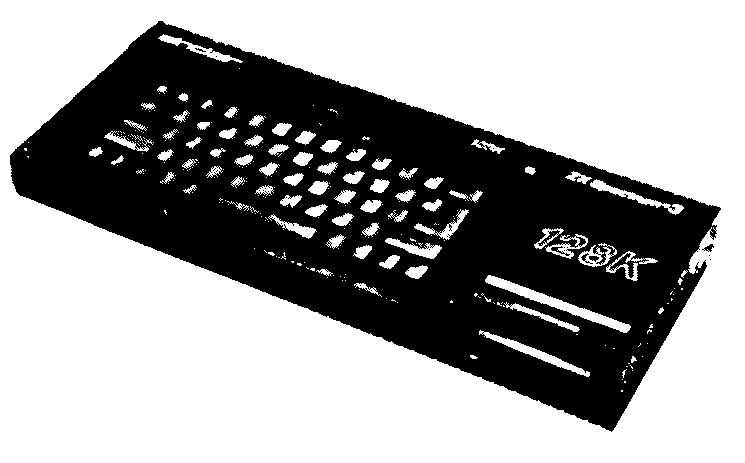
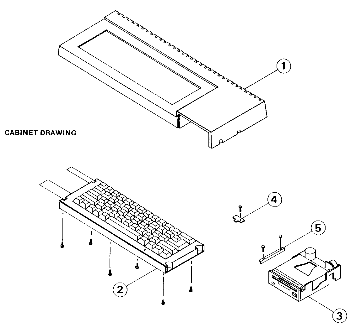
| 1 | Cabinet top | 173017 |
| 2 | Switch Keyboard Assembly | 173019 |
| 3 | Disc drive EME-156 | 190005 |
| 4 | LED PCB Assembly | 172004 |
| 5 | Bracket Disc Drive | 173021 |
| 6 | Socket I/O | 170022 |
| 7 | PAL modulator Block | 172020 |
| 8 | 8-pin DIN socket | 172021 |
| 9 | BT/Interface socket | 172022 |
| 10 | 6-way Power DIN socket | 173026 |
| 11 | 9-way Joystick port | 170023 |
| 12 | Reset Switch | 172017 |
| 13 | Cabinet bottom | 173018 |
| 14 | Main PCB Assembly | 173023 |
| . | Gun Foot | 173021 |
Diagnostic Flow Chart
This chart must be used in conjunction with the alignment procedures
This chart is for information only and does not guarantee an exact diagnosis. For warranty purposes and faulty drive mechanism must be returned to Amstrad for replacement. Service agents should not attempt any repairs on the mechanism or to it's PCB part number 270312
Index period------------N---------------Motor rotation
200+/- 5 msec?
     |
     Y
     |
Self-read error?--------N---------------Read Error
     |
     Y
     |
Write error?------------N---------------Write Error
     |
     Y
     |
Interchangeable---------N---------------Interchangeability Error
lead?
     |
     Y
     |
Disk Drive OK
Motor Rotation
     |
     |
Does motor--------------N---------------Power Supplied?
Rotate?                                  |          |
     |                                   |          |
     |                                   Y          N
     Y<--------------------------------<-|          |
     |                                              |
     |                                        Check Wiring
     |
     |
     |
Adjustable with---------N---------------Does it rotate
VR201?                                  normally by using------
     |                                  normal motor?         |
     Y                                       |                N
     |                                       Y                |
Adjust Time to 200                           |           Replace drive
+/- 1 ms                                 Replace motor
Read Error
     |
     |
Test with disk
EME - CF2
     |
     |
TR39 2F output-----------N-----Head touch OK?-----N-----Replace drive
>= 140 mV                           |
     |                              |
     |                              Y
     Y                              |
     |                              |
     |                          Is head output---N------Replace head assembly
Is TROO output------N           1 mV or more?
=< 220 mV           |               |
     |              |               |
     Y              |               Y
     |              |               |
Read/write error    |               |
in all tracks?->----+--Y---------->-Replace Drive
     |
     N
     |
Read error only-----------N-----------Seek Error----------N-------Replace drive
in Specific track?                        |
     |                                    |
     Y                                    Y
     |                                    |
Replace disk                              |
(inspect by drive)                     TROO output normal-----N-----Replace TROO
                                          |                         sensor
                                          |
                                          Y
                                          |
                                          |
                                       Replace drive
Write Error
     |
     |
Error Continous?-----------N-----Check action in----------OK-------Check action in
     |                           seek failure flow          |      read failure flow------+
     |                                                      |             |               |
     Y                                                      |      Amplifier System       |
     |                                                      |             |          Head system
     |                                                      |             |               |
Write waveform-------------OK----------------------------->-+             |               |
in TP1.2                                                                  |        Replace drive
     |                                                                    |
     |                                                                    |
    NG                                                                    |
     |                                                                    |
     |                                                                    |
Head Connector-------open---------Repair head connector                   |
open or short?                                                            |
     |                                                                    |
     |short                                                               |
     +--------------------------------------------------------------------+
     |
     |
Replace control PCB
Interchangable lead error
         |
         |
+ Off-track media----------N------------+
 lead test                              |
         |                              |
         |                              |
         Y                              |
         |                              |
         |                              |
- Off-track media----------N------------+-----------------Adjust positioning
 lead test
         |
         |
         Y
         |
         |
Index timing---------------N------------Adjust index timing
0-1000 usec
         |
         |
         Y
         |
         |
Media failure
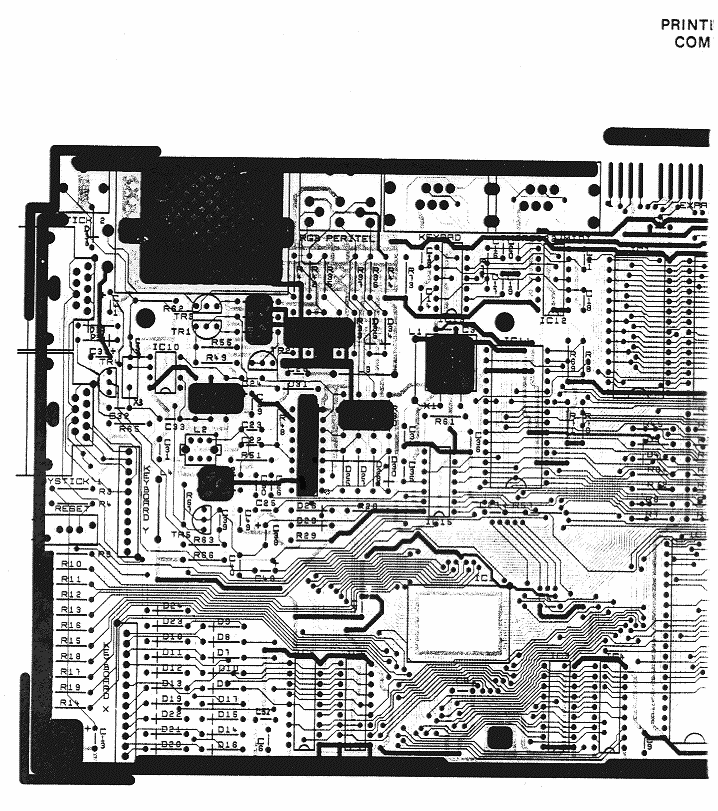
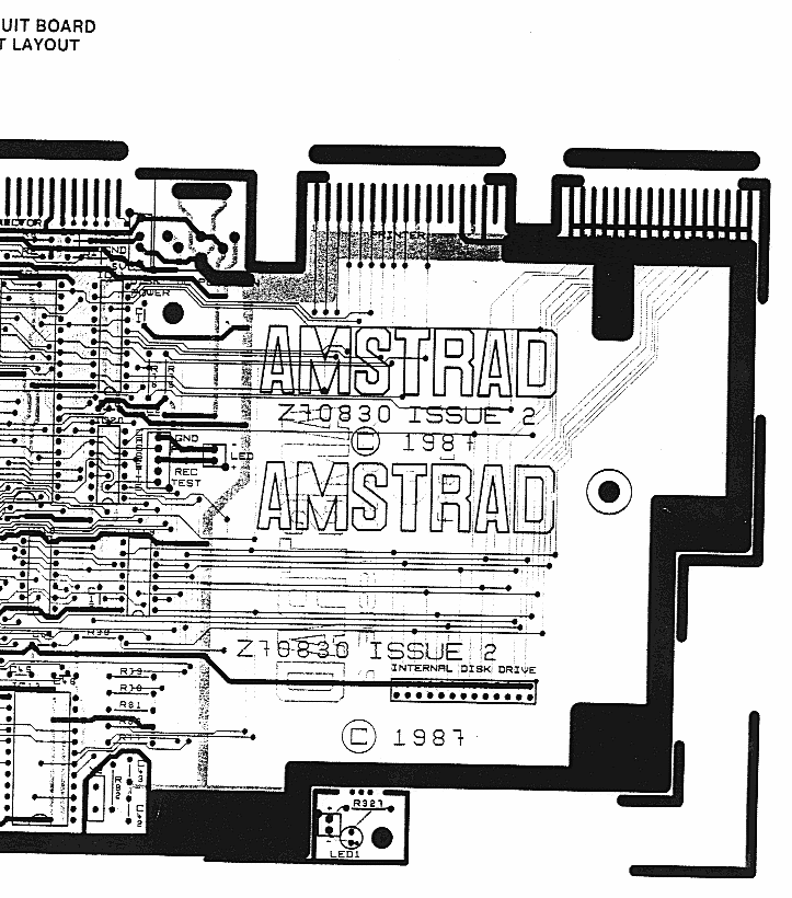
PCB
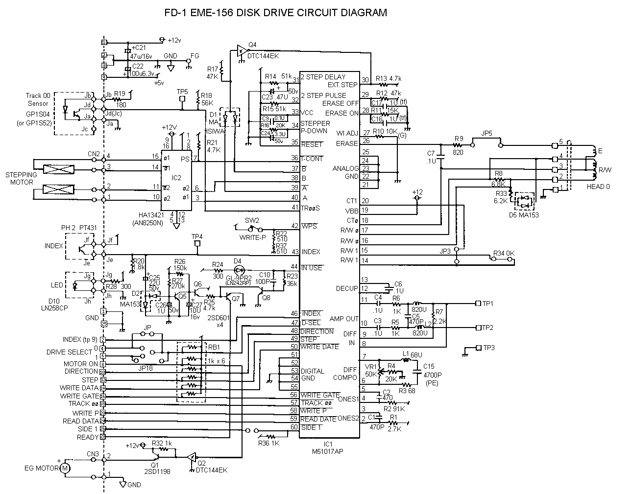
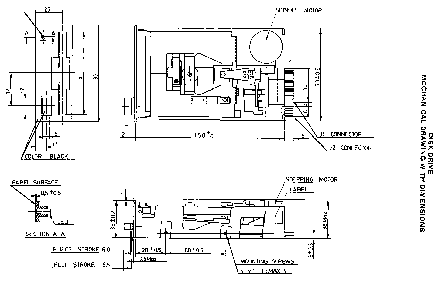
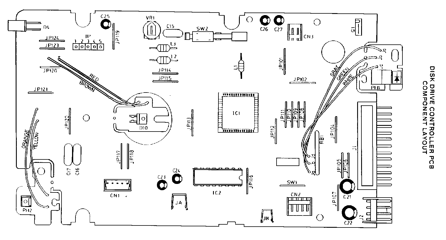
Disk Drive Diagrams
Software Errors
If a drive fault is reported the fault may be a software problem. Before investigating the drive please carry out the following checks to ensure it is not a software problem.
Detection and Correction of "Soft Errors"
Soft errors are usually caused by the following reasons.
- Random external noise of several microseconds or less.
- Minute off-tracking and shifting of write timing that are
not detected during the write operation which can cause
the soft error during the read.
To remedy such soft errors, take the following procedures at the controller side.- Repetitive reading on the track by 10 times or more until the data is restored.
- When the data is not restored by step 1, access the head to the adjacent track in the same direction as move previously, and thereafter return the head to the original track.
- Repeat the step 1.
- If the data is not restored by the above steps. the error cannot be remedied
Write Error
When an error is caused during the write operation, the error is usually detected during the next rotation through the read operation called "Write check".
To correct the error, repeat the write operation again and carry out the Write check.
If the result is still incorrect even after the write operation is repeated more than 10 times, either the disc or the drive are working incorrectly. To find out the trouble source, carry out the read operations with another track. Should the error still be found. change the disk and repeat the above procedures. Should error still be found, the drive should be considered defective. If the error is removed, the original disk must be defective. Discard it.
Seek Error
- Step motor or step motor drive circuit is defective.
- The torque of the carriage is not correct.
Restoration procedures from the seek error.
make the re-calibration to the track 00. Then, carry out the re-seek to the original track
Notes:
- Always ensure the head is clean.
- Index/Sector Factor (Ready Defect)
As the unit has Optional Read Output
It is normally not ready until 2 revolutions are made after the
disk insertion.
Diagnostic Flow Chart
START--<--------------------------------------------------------------------------+
     |                                                                            |
     |                                                                            |
CHECK TV TUNED OK. TRY                                                            |
CHANNEL 36. VOLUME UP                                                             |
     |                                                                            |
     |                                                                            |
CONNECT PSU TO 240V                                                               |
AC MAINS. CONNECT TO                                                              |
TV SOCKET                                                                         |
     |                                                                            |
     |                                                                            |
HOLD DOWN BREAK KEY                                                               |
AND PLUS IN 9V LEAD                                                               |
INTO COMPUTER                                                                     |
     |                                                                            |
     |              NO                           NO                               |
RED LED LIGHTS UP?------------>-MAINS FUSE OK?-------->-REPLACE FUSE----------->--|
     |                                |                                           |
YES  |                                |                                           |
     |                NO              | YES                                       |
PICTURE/SOUND ON TV?----------->-+    +-----------------CHECK LED, PCB---->--+    |
     |                           |                      CONNECTOR            |    |
YES  |                           |                                           |    |
     |                           |           NO                              |    |
PRESS AND RELASE                ANY PICTURE---------->--CHECK MODULATOR,--->-|    |
RESET BUTTON                    AT ALL?                 DC-DC CONVERTOR      |    |
     |                           |                                           |    |
     |           NO              |YES                                        |    |
MENU APPREARS?---------+         |                                           |    |
     |                 |         |                                           |    |
YES  |                 |         |                                           |    |
     |                 |         |          YES                              |    |
PRESS DOWN ARROW       |        ANY SOUND?--------------CHECK ULA, CPU---->--|    |
     |                 |         |NO                    RAM, TEA 2000        |    |
     |           NO    |         |                                           |    |
BLUE BAR ON MENU---+   |        CHECK MODULATOR---------------------------->-|    |
MOVES?             |   |        SOUND COIL TUNING                            |    |
     |             |   |                                                     |    |
YES  |             |   +------>-CHECK ROM------------------------------->----|    |
     |             |                                                         |    |
SELECT 128K BASIC  |                                                         |    |
PRESS ENTER        +---------->-CHECK KEYBOARD----------------------------->-|    |
     |             |            CONNECTORS, ULA                              |    |
     |             |                                                         |    |
TEST ALL KEYS      |                                                         |    |
     |             |                                                         |    |
     |    NO       |            RECTIFY AND RETEST----<----------------------|    |
ALL OK?------------+              |                                               |
     |                            |                                               |
YES  |                            |                                               |
     |                            +-------------------------------------------->--+
DO TAPE TESTS
SPECTRUM +3 SELF DIAGNOSTIC TESTS
The Spectrum +3 test software comes on a rom board. This should be plugged into the Expansion I/O slot of the +3. The +3 should also have a loopback cable plugged into the KEYPAD and RS232 sockets, two joysticks plugged in, and monitor, TV and audio amp connected.
Turn the machine on. One of two things will happen.
- A test card with some text will appear. Follow the instructions on the screen.
- No text or testcard. In this case, note the color of the edge of the screen. It will either be a steady color or flashing regularly with a predominant color. Consult the table below to find out which RAM chip has (probably) failed.
Color STEADY FLASHING
             BLACK   IC 17     IC 32
             BLUE    IC 18     IC 31
             RED     IC 19     IC 30
             MAGENTA IC 20     IC 29
             GREEN   IC 21     IC 28
             CYAN    IC 22     IC 27
             YELLOW  IC 23     IC 26
             WHITE   IC 24     IC 25
If you follow the instructions on screen from the first occurrence, then everything should be self-explanatory, The RAM test, if it finds a fault, will give two numbers. The first is the address at which the fault was found, and the second is the bank of memory which contained the address. If the address is zero, then it is probably not a RAM fault, but a paging hardware problem. Note that there is no way to fail the keyboard test - if a key won't respond then you can progress no further.
The cassette test comes in two parts. The first cassette test is similar to the ULA sound test, and is the last test in the ROM program. The tone it asks you to hear is much quieter than the other noises. The second cassette test comes on a tape and is used when the BASIC is running. Turn on the Spectrum, wait for the menu to appear and then press ENTER. Then start the test cassette. After a short while, the words PROGRAM: Loading... should appear, and shortly afterwards some instructions will appear on the screen. Follow these to test the cassette unit.
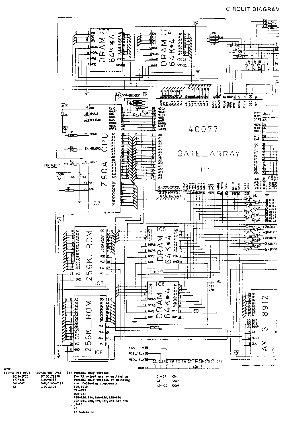
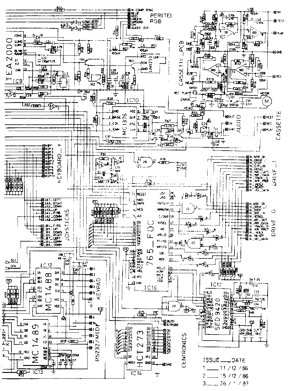
Circuit Diagram
Electrical Parts List
Integrated Circuits
Reference no. Description Part #
IC1		Gate Array 40077   		40077
IC2		Z80A CPU   			40080
IC3-6		64K x 4 D.RAM  			173001
IC7		256K ROM VERSION  		173002
IC8		256K ROM VERSION 2  		173003
IC9		TEA2000  			172048
IC10		MC1376  			172049
IC11		AY-3-8912A  			40001
IC12		MC 1488 QUAD RS232 DRIVER       172039
IC13		MC 1489 QUAD RS232 REC  	172038
IC14		74HCT273   			173004
IC15		74HCU04  			40005/A
IC16		765 Floppy Disk Controller   	40018
IC17		SED 9420  			171034
IC18		74HC704   			173008
IC19		74HC14  			171033
IC20		74HCT00    			40008
		IC40 Pin Socket 		170121
		IC28 Pin Socket    		170120
Transistors
TR1		TRBC3083/BC558B			172032
TR2-5		TRBC239B/BC549B			50008
Diodes
D1-4,6-31,33-35	D1N4148				190715
                LED Red LTL 321lA		172004
Miscellaneous
Xl		CrystaL 35.4690MHz		172067
X3		6MHz Ceramic Resonator		173011
X2		16.000MHz Ceramic Resonator	173013
		Modulator UHF			172020
		Aerial Lead			172065
		9 Way D Plug			173015
		Power Supply Unit		173034
Coils
L1		Inductance 2.2uH		172058
L3,4		Inductance l00uH		172060
L2		RF Choke 4.43MHz 4097		173016
Carbon Film Resistors
R45		47ohm				10020
R4,50,51,73	l00ohm				10032
R31-33.35-37,41	l50ohm				10036
R34		470ohm				10048
R77-81		680ohm				10052
R9-13,47	820ohm				10054
R6-8,44,46	lkohm				10061
R54,68-71,74	1kohm				10061
R14-19,56,60,85	lk5ohm				10065
R42,62,65,72	2k2ohm				10069
R52		3k3ohm				10073
R49		3k9ohm				10075
R53,63,64	4k7ohm				10077
R55,86		6k8ohm				10081
R1-3,5,20-30	10kohm				10085
R43,57,66,75,76	10kohm				10085
R59		l5kohm				10089
R83		33kohm				10097
R48		36kohm				172077
R58		39kohm				10099
R67		47kohm				10101
R84		68kohm				10105
R61,82		lMohm				10147
Ceramic Capacitors
C42,43		7 pF NPO			173027
C32		10 pF NPO			173028
C34		22 pF NPO			173029
C36		22 pF				150511
C22		33 pF NPO			173030
C33		47 pF NPO			173031
C25,26,49,50	l00 pF				1422144
C14-17		220 pF				400107
C24		330 pF NPO			173032
C18-21,44	0.00l uF			24027
C23,35,47	0.01 uF                         24011
C45		0.047pF				24015
C1-7,9-12,28	0.luF				171058
C31,37,39,40,46 0.luF				171058
Electrolytic Capacitors
C13,27,38,41	luF/50V				20062
C8,29,30	l00uF/16V			20028