Concise Atari ST 68000 Programmer's Reference Guide
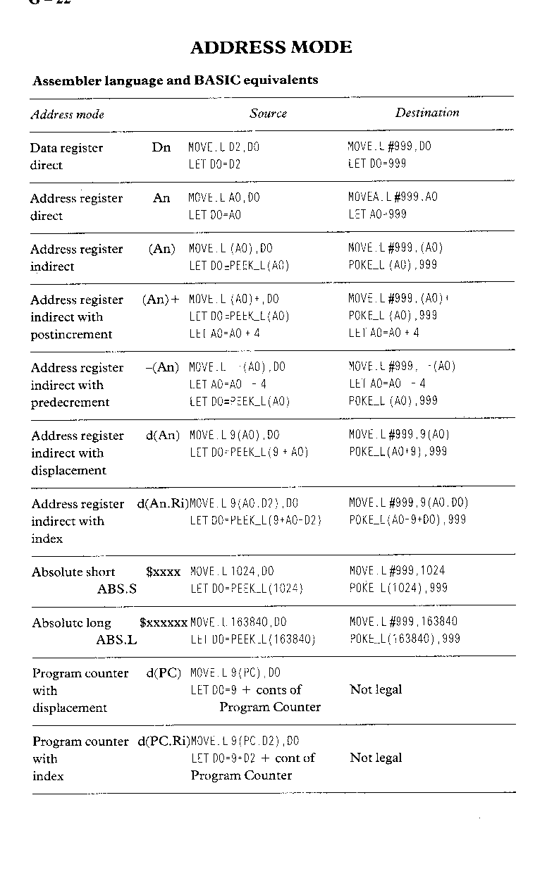
Each Motorola MC68000 instruction is presented, many in terms of equivalent BASIC Instructions or assembler routines. The similes are for clarification of the use of each instruction; there is no access to the data or address registers (Dn or An respectively) or the condition codes from BASIC and therefore the examples which make use of these registers, and most of the effective address modes (ea), cannot be taken literally.
Key
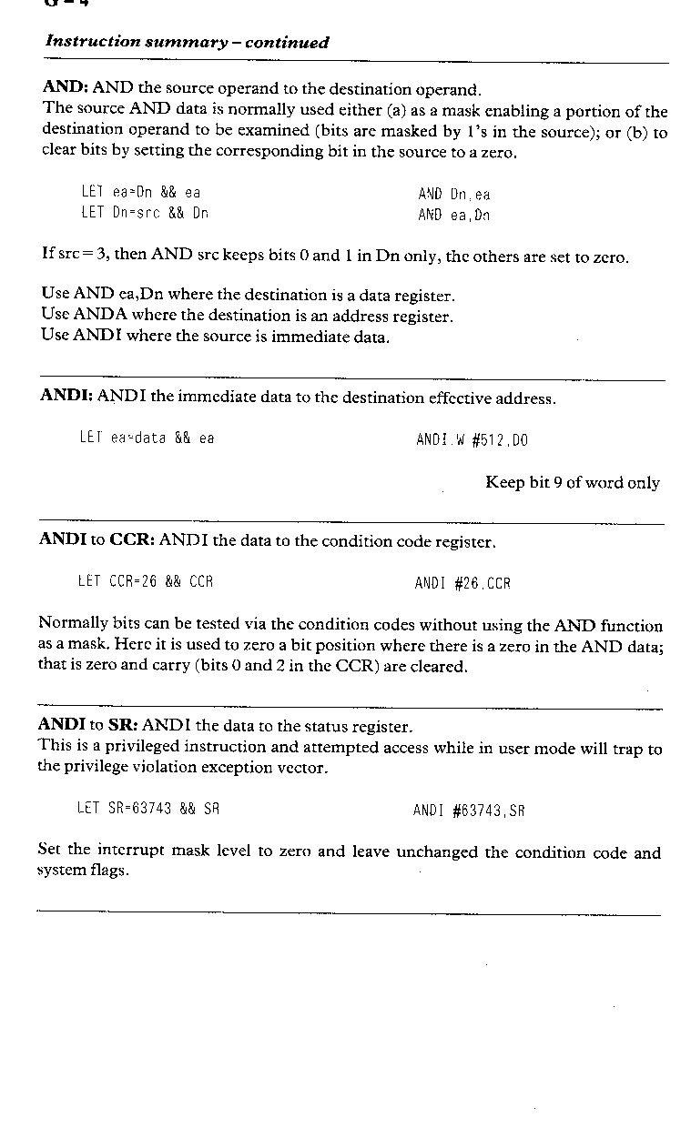
&& bitwise AND
^^ bitwise EOR
|| bitwise OR
Add two byte-sized binary coded decimal numbers and the Extend bit; a dollar sign is used to indicate a BCD number. Clear the extend bit and set the zero bit before performing this instruction which is limited to byte-size data register operations; multi-byte additions are performed more easily in memory.
BCD addition			DATA Register		Memory
				Addition		Multi-byte Addition
				Byte only
							MOVE #4, CCR
$7		$27					ABCD   -(A0),-(A1)
ABCD $6		ABCD $16	ABCD D0,D1		ABCD   -(A0),-(A1)
$13		$43					ABCD   -(A0),-(A1)
Note that the z-flag is cleared if the result is non-zero, otherwise it is unchanged and that in memory additions the data must be stored with the most significant digit lower in memory and the address pointers initially set to the byte above the low-order BCD digit in memory, as the only available addressing mode is predecrement.
One of the integers must be the contents of a data register.
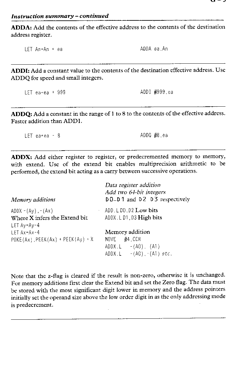
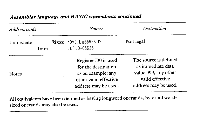
LET Dn=Dn + ea			ADD ea, Dn
LET ea=ea + Dn			ADD Dn,ea
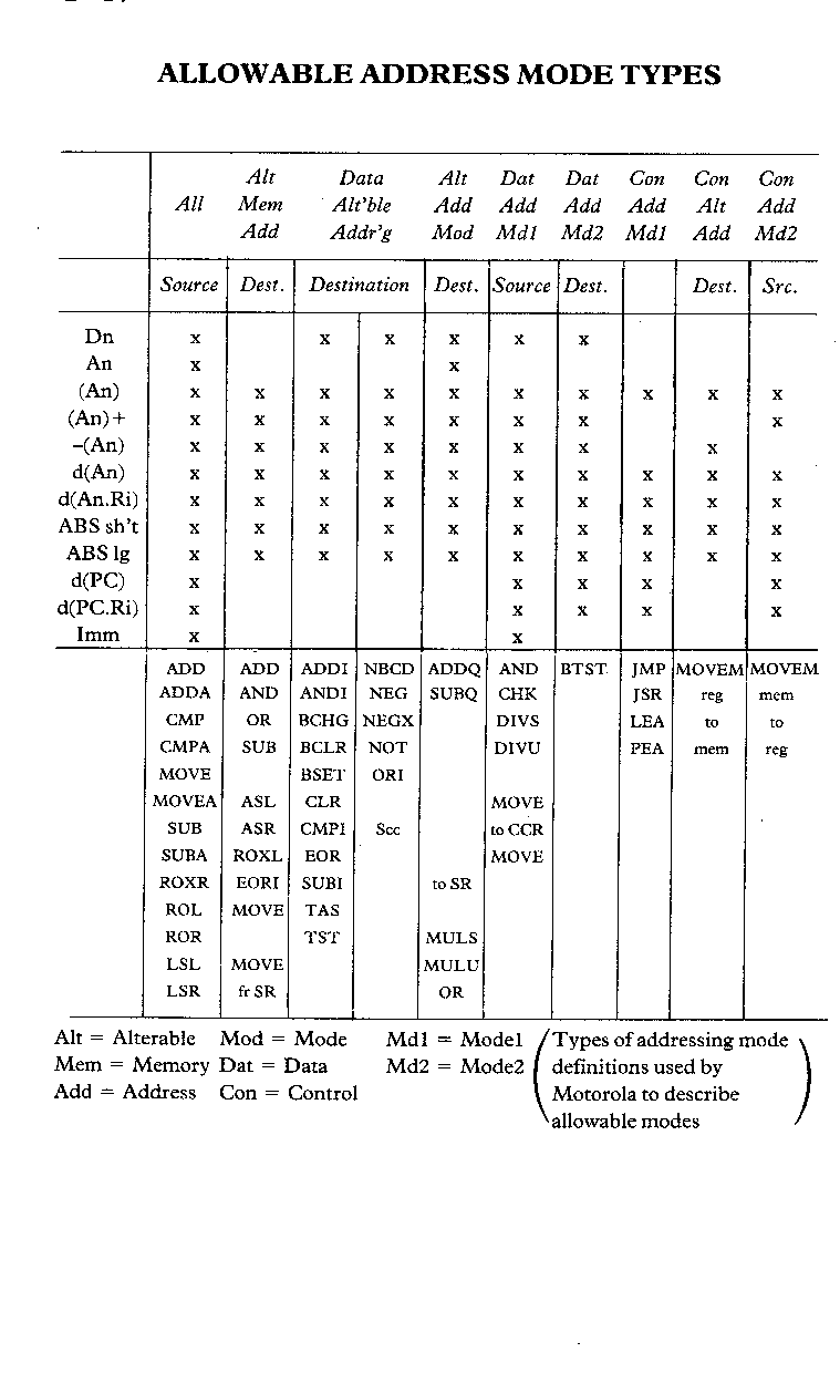
Use ADD ea,Dn where the destination is a data register.
Use ADDA where the destination is an address register.
Use ADDI or ADDQ where the source is immediate data.

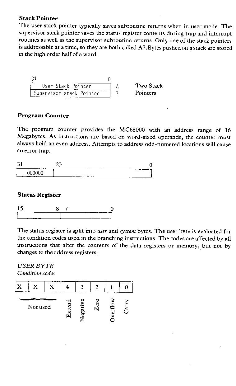
The unused bits in the status register are read as zero. They are available for the MC68020 instruction set.
SYSTEM BYTE
| 15 | X | 13 | X | X | 10 | 9 | 8 | |
| | | | | Interrupt mask | ||||||
| | | Supervisor state | |||||||
| Trace mode | ||||||||
Organisation of addresses in memory
| Memory start | ||
| Word | High byte 15-8 | <-- Even address |
| Low byte 7-0 | +1 | |
| Long word | High byte 31-24 | <-- Even address |
| 32-16 | +1 | |
| 15-8 | +2 | |
| Low byte 7-0 | +3 | |
| Byte | Byte | <-- Any address |
| Memory end |
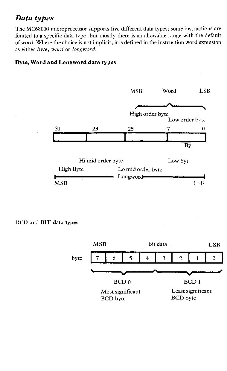
For word and longword memory operations, the high byte is on a word boundary (even address), the following bytes are in order higher in memory.
Stack
By convention, system stacks grow towards lower addresses in memory.