Color Computer Technical Reference Manual
Problems with the TRS80 Color Computer may be divided into two major categories, I/O problems and "dead" computer problems. If the computer will display the signon message, then the Color Computer Diagnostic ROM may be used to isolate the section of the computer that is bad. If, however, the computer displays garbage on the TV screen, then one of the major logic functions has failed.
A “dead" computer (garbage on the display or no display) indicates a major malfunction of the machine. In this case, the first thing to check is the power supply voltage levels. These may be checked at the following points.
+ 5 volts - Test Point 12
- 5 volts - Test Point 11
+12 volts - Test Point 9
-12 volts - Test Point 10
Ground - Test Point 3
Or if you are having problems finding these test points, check the voltages on one of the RAM chips (U20 - U27).
Pin 1 = - 5 volts (minus five)
Pin 8 = +12 volts
Pin 9 = +5 volts
If one of the power supply voltages is off by more than 5%, determine if the fault is due to a failure within the power supply or to another section affecting the power supply. Refer to the Power Supply section for possible causes of the problem and tips on how correct it.
If all of the voltages are correct but there is no display what-soever on the TV screen, a video problem is evident. Refer to the Video Interface section for hints on fixing this problem.
If all of the voltages are at the proper level but you still have a screen full of garbage, then you should try chip substitution. Try replacing the following chips.
U20 - U27
U10
U1
U4 and U8
U3Dynamic RAM chips
MC6883 Dynamic RAM controller
MC6809E CPU chip
MC6821 PIA
MCM68A364 ROM
Make sure you replace the RAM chips with the same size (4K, 16K, or 32K) as the original chips.
If the computer still displays garbage after the chip substitution, the most likely problem is a short on the address or data bus. Remove the ground plane and carefully look at the insulator and the PC Board. It is possible that one of the IC leads has punctured the insulator and is shorting out. If the computer operates without the ground plane, then trim the excess leads on the bottom of the board. Make sure you don't leave any loose material on the bottom of the board when you replace the ground plane.
If the computer still fails to operate after removing the ground shield, you will need to start a methodical checking process. First, make certain that the CPU (U1) is running by using an oscilloscope to look at some of the address lines (pins 8 - 23) and the data lines (pins 24 - 31). They should normally be changing states fairly fast. If they are not changing at all, then one of the control or clock signals to the CPU is wrong. Pins 34 and 35 of U1 should have a 0.89 MHz clock input to the CPU (U1). Pins 2, 3, 4, 40, and 37 should all be high. Pin 39 should be low.
If the CPU is running then there is some short or open on the address or data bus. Check to make certain that all of the sockets are properly soldered into the board. It is possible that one of the pins on a socket has been bent under. Also check for any defect on the board such as a solder short or a broken etch.
It is possible that the Diagnostic test may designate a part of the circuit that is not the faulty part. If the designated part does not seem to be causing the problem, the following notes may help.
A video problem is usually caused by U7 (MC6847), however, a video failure may also be caused by U10 (MC6883). The chip U10 could also be the cause of a RAM problem. A RAM connected failure of U10 would be indicated if repeated trys of the RAM test showed random chip failures, or if replacing the indicated RAM chip does not fix the problem.
The video interface is composed of four primary parts U6, U7, U12, and U5. Also U10 is used to provide the video address lines to the RAM. The most likely source of a problem is U7 (MC6847). However, it is always a good idea to isolate the source of a problem before trying to desolder chips.
If the problem is no picture or a distorted picture, then a new switch box and cable should be tried. If you still do not have a picture, then use your oscilloscope to look at U7, pin 28. You should have a video signal at this point. (Refer to the Video Interface section of the Theory of Operation for an example of what this signal should look like.) If you do not have a video signal, check U7, pin 33. There should be a 3.579 MHz clock signal at this point. If you have a clock signal but no video at pin 33, then U7 is bad. (You might also check. pin 17 just to make sure the chip has +5 volts.)
If you have a video signal at pin 28 of U7 but still have no TV picture, the next point to check is U12, pin 12. Again there should be a video signal at this point. If you do not have a video signal on pin 12 then check the inputs to the chip. (Pin 2 = 3.579 MHz clock; pin 11 = +6 volts; pin 9 = input video; etc.) Also check for +8 volts on the top side of R16. If all the inputs are present then U12 is probably bad.
The last place to check the video signal is on the modulator input (pin 1 of U5). If you have the video signal at the point and at the proper DC level, then U5 is probably bad. If the video signal is not present, then 01 or one of the associated biasing resistors is probably the faulty part. (Make sure you check for +8 volts on the collector of Q1.) If the video signal is at the wrong DC level, try adjusting R21. If the signal will not adjust to the proper level then most likely one of the biasing resistors for Q1 is bad. U12 may also cause this problem if the output from pin 12 is out of spec.)
If the video problem is associated with only one mode of operation (graphics, semigraphics, or alphanumerics) then one of three chips is causing the problem; U6, U7, or U10. If some of the dots are missing from alphanumeric characters then U7 is faulty. If some characters are being displayed as the wrong character, then the correct data is not being supplied to the data inputs to U7. U6 latches this data so it may be causing the problem or there may be a short on the data lines.
if some of the graphics modes do not work, then check pins 27, 29, 30, and 35 of U7. These pins should change from high to low as you change from one mode to the next. These signals are supplied from U4, which could be causing the problem if signals are changing properly. If these pins all seem to change, then the problem is caused by U10 or U7. (Since U10 is in a socket, try replacing it first.)
Before you tear into the computer to fix a joystick related problem, try a second set of joystick controllers to make sure the problem is in the computer. The only possible fire switch problem, that will not also show up as a keyboard problem, is if L2 or L3 is broken or the etch is cut or shorted.
To troubleshoot the joystick interface you should have the Diagnostic joystick test running. If the problem is missing blocks, then one of the bits going to the D/A converter is not changing properly. Set both joysticks to the bottom right corner. Use an oscilloscope to check the D/A pins from U4 (pins 4 through 9). If all of the pins are changing then U4 is good. Also check the output pins of U2, they should all be changing. Finally, look at the output of the D/A converter (U14, pin 8). At this point you should see an even stairstep function. If one or more of the steps is twice as large as the other steps then one of the resistors is bad.
If the problem is that the joysticks do not work in one or more directions, connect an oscilloscope to U9, pin 9. With the Diagnostic joystick test running you should see four DC voltage segments. One dimension on each joystick should affect one of the segments. Try moving the joysticks around to check this. You can look at the DC voltages directly from the pots at the input pins of U9. If the inputs of U9 are changing (including select pins 6 and 7) but the output is not, then U9 is probably faulty.
if U9 seems to be working properly then check U14. Set both joysticks to the center. Checking pin 8 of U14 you should see an even stairstep function going up to approximately 2.5 volts. The output, pin 14, should be switching each time the stair-step on pin 8 peaks. If the output is not switching, then U14 is not working.
if you are having cassette problems, run the joystick test first to confirm that the D/A is working. If the computer passes the joystick test then there are only three other components in the output circuit that could be failing; R41, R42, or C82.
The cassette input circuit is a simple sinewave-to-squarewave converter. To test it you will need a long tape of consistent data. By running this tape, your should be able to compare the input sinewave to the output squarewave and see if the converter is working. If this circuit is working, the only other part involved in the cassette interface is U4.
If the problem is motor control, relay K1 is most likely bad. To test this, check to see that the collector of Q4 is switching as you use the MOTOR ON and MOTOR OFF command. If it is not switching, Q4 or the PIA output pin is faulty.
The keyboard interface is a very simple electronic circuit. The only digital part ised is US. Usually a keyboard failure will be caused by a mechanical failure of the keyboard itself, or a short or open in the cable. Mechanical failures will usually be only one isolated key failing. Cable failures will cause an entire keyboard row or column not to work.
The RS232 Interface utilizes three level converter circuits. Isolating the problem in these three circuits will be a simple matter of comparing the input to the output.
Connect a DIN-type plug to the I/O serial jack to short together pins 1, 2, and 4. Now type in the following test program:
5 POKE 65312,2
10 FOR X = 0 TO 10: NEXT X
15 POKE 65312,0
20 FOR X = 0 TO 10: NEXT X
25 GOTO 5
Run the program and check pin 2 of U15; a switching TTL waveform should be present. Pin 6 of U15 should have the same waveform except that it will be switching from+11 volts to - 11 volts. Also check pins 4 and 6 of U14. These pins should have the same waveform switching from 0 to +10 volts. The outputs of U14, pins 1 and 2 should show the original TTL signal when the test program is running.
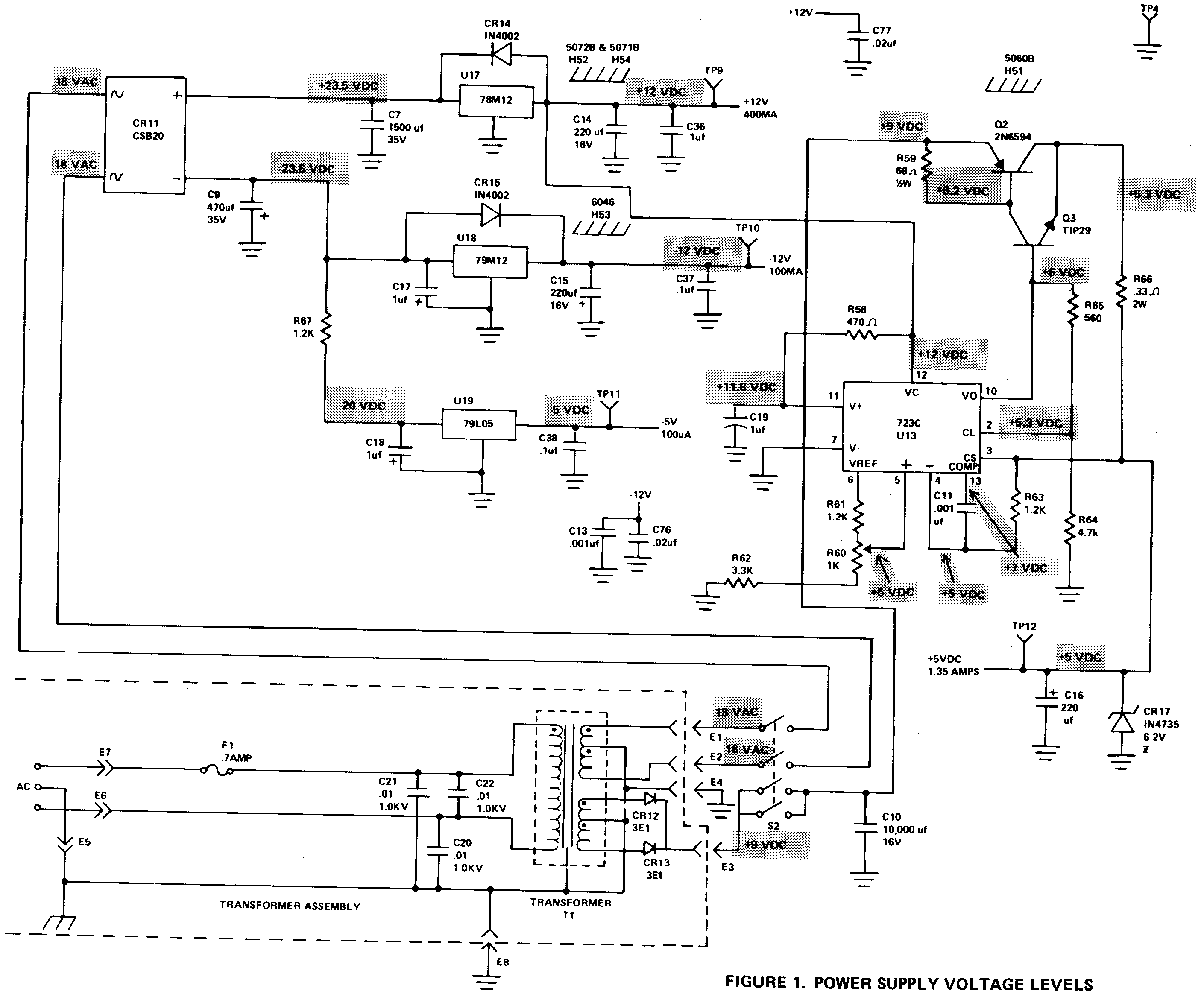
If you have a power supply problem, usually only one of the four supply voltages will be bad. However the +5 volt supply is powered by the +12 volts supply, so a bad +12 volt supply will also cause the +5 volt supply to fail. Anytime you have a supply that is at zero volts, you should measure the resistance between ground and that supply (with power off). This will quite often show that you have a short to ground. Please note that the +5 volt supply has an overvoltage diode, CR17, which will automatically short to ground in the case of an overvoltage condition on the +5 volt power supply.
If the problem is not an external short to ground, refer to Figure 1 and check the voltages along the affected power supply. If the voltage is bad at one output of CR11, the regulator or the filter capacitor is bad. If both voltages are bad then CR11 is faulty. Check that CR11 has the correct input voltage from the transformer. If the voltage is correct at the input to the regulator and the output is not shorted, then the regulator is bad.
The -5 volt supply is more complex than the other supplies. However, you may use the same troubleshooting method as with the other supplies. Check the voltage from the input to the output of the supply until you find the point where the voltages are wrong. This will usually point to the bad device. A faulty +5 volt supply may be caused by U13, Q2, or Q3.
If the +5 volt supply was shorted to ground by CR17 then there is also a problem with the regulator circuit. To correct this, remove CR17 and break the +5 volt line while trouble-shooting the supply. Removing R66 will break the +5 volt output line.
FIGURE 1. POWER SUPPLY VOLTAGE LEVELS