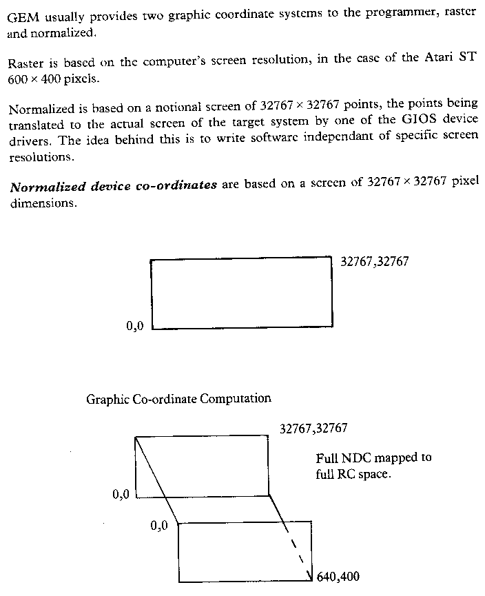
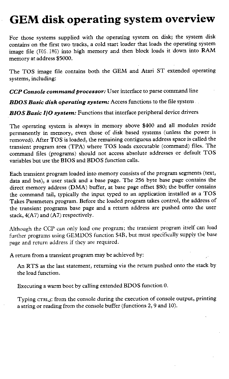
The Atari ST operating system is in many ways functionally similar to CP/M 68K, with extensions for handling a mouse, sound, the MIDI interface, an intelligent keyboard and joysticks. A graphics environment manager (GEM) provides additional single-user support for windows and communications via VDI and AES extensions, which accommodate graphics and an applications environment. Program transportability is maintained by splitting the operating systems into machine independent (BDOS, VDI and AES) and machine dependent basic input/output utilities (BIOS and A-line routines).
The ST programmer is given access to the VDI primitives via the A-line routines for much greater graphic application speed.
The disk operating system (DOS) enables routines to access the disc drives with support for existing single user programs, file locking to ensure safe updating, read only and unlock facilities. The access manager improves the file handling with a library of routines that permit indexed files through a tree structure to ensure high operational efficiency. Other functions available are; both data and indexed file system initialisation update, duplicate keys and an index file search. Runtime errors may be handled internally, or there is the option to stop and correct the error.
Programmable segments of TOS
Machine BIOS
dependent
input/output
routinesBIOS A-line routines General
operating
systemsBDOS
Basic
Disk
Operating
SystemGEM VDI
Virtual device interface
GEM AES
The application environment (AES) multitasks using a time-slicing technique and supports a database file management system, real time data acquisition, communications and process control.
The virtual device interface (VDI) allows the use of peripheral independent device drivers and provides a high degree of assistance for advanced user interfaces.
The BIOS consists of all the machine dependent I/O routines of Digital Research’s GEM and additionally provides access to the A-line routines for fast graphics. The I/O functions can be categorized as follows:
GEM BIOS:
System I/O:
Parameter block initialization
Console I/O: Data I/O & query
Disk I/O: Memory/disk transfersAtari ST extended BIOS:
Port I/O: Configure RS232, mouse, MIDI & sound port
Screen I/O: Get screen parameters
Disk I/O: Memory/disk transfers
Keyboard I/O: Keyboard communicationsA-line routines:
Pixel graphics
Line graphics
Sprite graphics
Bit block transfer
Mouse handler
The disk operating systems permits the machine independent routines to access the disk drives and handle file management through the following functions:
The VDI provides a set of graphic function calls that allow portability across physical hardware. Not all the standard VDI calls are implemented on the ST, the VDI tables Chapter 3 are annotated to show those that are missing.
The AES (application environment services) are a series of utilities that handle graphic based inputs to the user application. For example, instead of asking for INPUT - the screen displays graphically a menu of options which may include a clock, a file and perhaps a disk, these items being given a pictorial representation that is called generically an ‘Icon’. To select one, the user simply moves the cursor, which may look remarkably like an arrow, and places it on the required icon using the mouse and presses the trigger button. The AES routines are put into groups called libraries as follows:
The desktop application provides the support for windowing, control and synchronisation of asynchronous events, interprocess communication, loadable device drivers and device independent graphics support. The clock application date stamps each file on creation or modification.
| 000000 | Supervisor RAM variables | 0 | Supervisor access only |
| 000400 | OSBSS user RAM variables | 1024 | |
| 000800 | 512K RAM | 2048 | |
| 080000 | 1024K RAM | 524288 | |
| 100000 | 1048576 | ||
| FA0000 | ROM Area | 16384000 | |
| FF8800 | Memory mapped input / output |
16746596 | |
| FFFFFF | 16777215 |
| FF8000 | Memory | 16744448 |
| FF8200 | Display | 16745060 |
| FF8400 | Reserved | 16745572 |
| FF8600 | DMA/Disk | 16746084 |
| FF8800 | SOUND | 16746596 |
| FFFA00 | MK68901 | 16775680 |
| FFFC00 | MC6850 | 16776192 |
| FFFFFF | 16777215 |
| FA0000 | 128K System ROM |
16384000 |
| FC0000 | 192K Cartridge ROM |
16515072 |
| FF0000 | 16711680 |
References to the bottom 2K of memory and the I/O space are classed as supervisor references and attempted access from user mode will cause an error exception trap.
| $000 | Reset init SSP | 0 | Supervisor
space The system variables are in |
|
| $004 | Initialise PC | 4 | ||
| $008 | Bus Error | 8 | ||
| $00C | Address error | 12 | ||
| $010 | Illegal Instruction | 16 | ||
| $014 | Zero divide | 20 | ||
| $018 | CHK instruction | 24 | ||
| $01C | Trap instruction | 28 | ||
| $020 | Privilege violation | 32 | ||
| $024 | Trace | 36 | ||
| $028 | Emulation 1010 | 40 | A-lines routines entry | |
| $02C | Emulation 1011 | 44 | Used by some AES functions | |
| ... | ||||
| $03C | Unit interrupt vector | 60 | ||
| ... | Unused vectors point to system-critical error handler. | |||
| $060 | Spurious interrupt | 96 | ||
| $064 | Interrupt level 1 | 100 | ||
| $068 | Interrupt level 2 | 104 | Horizontal blank sync. | |
| $06C | Interrupt level 3 | 108 | Normal interrupt level | |
| $070 | Interrupt level 4 | 112 | Vertical blank sync. | |
| $074 | Interrupt level 5 | 116 | ||
| $078 | Interrupt level 6 | 120 | MK 68901 MFP | |
| $07C | Interrupt level 7 | 124 | Non maskable interrupt | |
| $080 | Trap #0 vector | 128 | ||
| $084 | Trap #1 vector | 132 | ||
| $088 | Trap #2 vector | 136 | ||
| $08C | Trap #3 vector | 140 | ||
| ... | ||||
| $0B0 | Trap #12 vector | 176 | ||
| $0B4 | Trap #13 vector | 180 | GEM BIOS | |
| $0B8 | Trap #14 vector | 184 | Atari ST BIOS extensions | |
| $0BC | Trap #15 vector | 188 | ||
| $0C0 | ... | 192 | ||
| $100 | 256 | MFP vectored interrupts | ||
| $200 | 512 | Reserved for OEMs | ||
| $400 | 1024 | System parameters and variables | ||
| $800 | 2048 |
| Functions controlled | |||
| FF8000 | Memory | 16744448 | Memory size |
| FF8200 | Display | 16745060 | Video address. Field rate. Video mode & palette. |
| FF8400 | Reserved | 16745572 | |
| FF8600 | DMA/Disk | 16746084 | Floppy/hard disk DMA |
| FF8800 | SOUND | 16746596 | PSG 3-channel
sound, noise tone, amplitude and envelope. RS232. Parallel port. Disk write. |
| FFFA00 | MK68901 MFP |
16775680 | System clocks. System interrupts. |
| FFFC00 | MC6850 ACIA |
16776192 | Keyboard and MIDI I/O |
| FFFFFF | 16777215 |
The pseudo multitasking kernel can support one primary application and one of three desk accessory programs.
The main application may be GEM or DOS such as GEM desktop application or a word processing package etc.
| Screen Environment | ||||||
| | | | | | | | | |||
| Primary Desk Application |
Desk Acc 1 |
Desk Acc 2 |
Desk Acc 3 |
|||
A minimum space allocation of 128K.
A desk accessory is an application that does not take over the entire display screen, running in a specially designed window. The calculator is a typical accessory.
Only one desk accessory program may be active at a time, and will only load if at least 128K of RAM is left for the primary application.
The dispatcher divides CPU time between primary applications and background processes. These jobs are put into lists; ‘Ready for processing’ and ‘Not ready’, and are serviced on a round robin schedule with the current process at the head of the list running. Not ready processes may be waiting for a key press, mouse movement or trigger, time lapse etc.

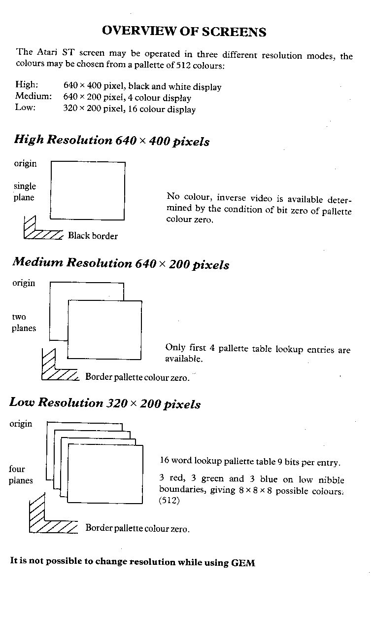
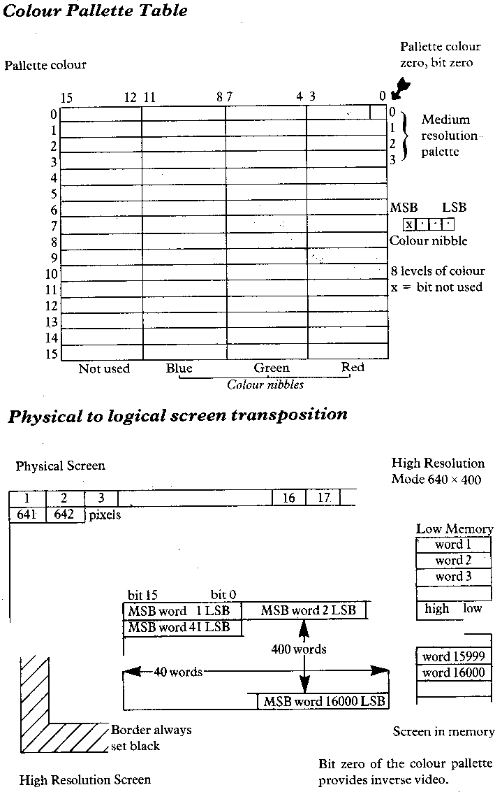
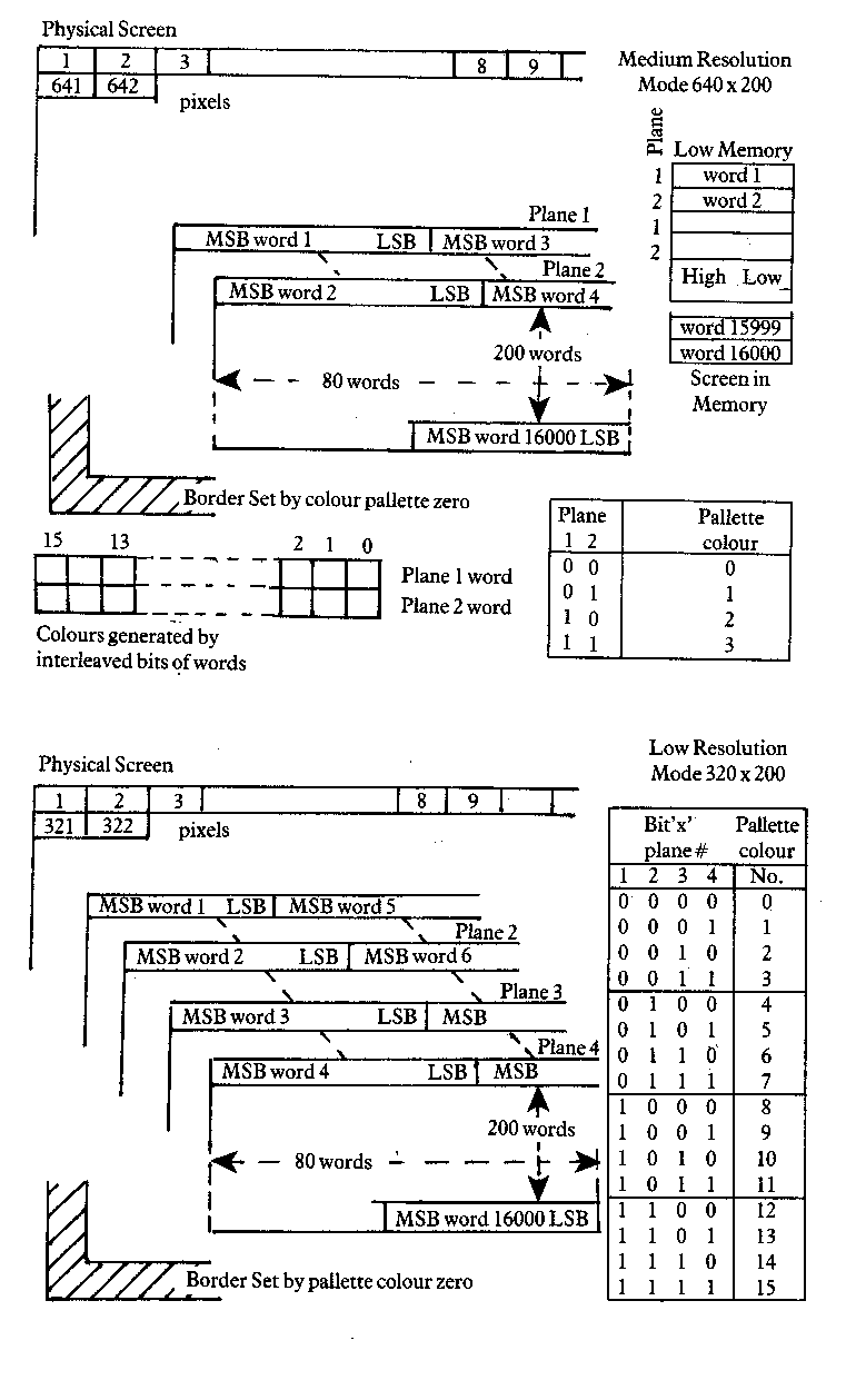
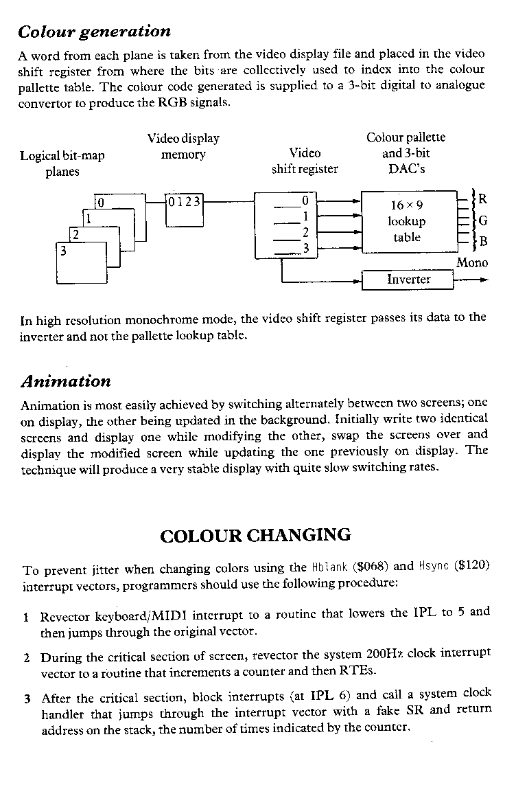
The Atari ST may be operated in three different resolution modes. The colours may be chosen from a palette of 512 colours.
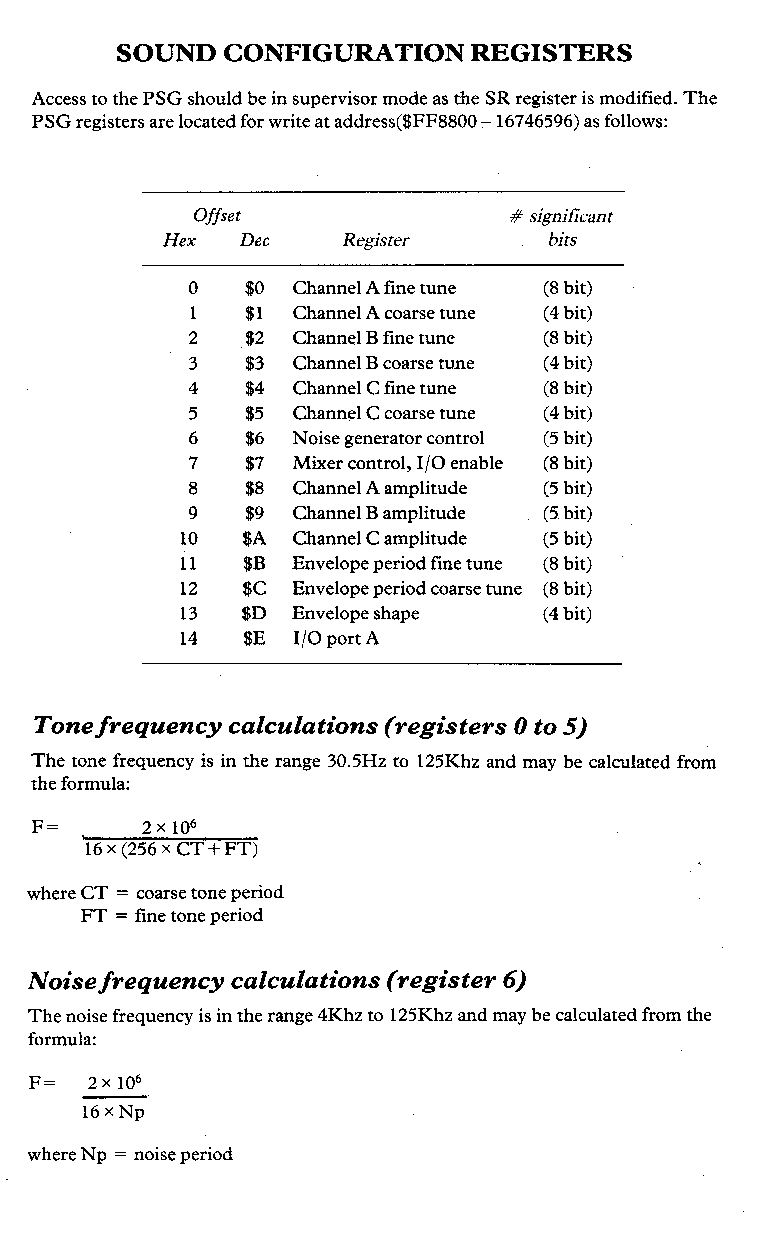
Sound is generated via a Yamaha YM2149 programmable sound generator. The PSG contains three tone generators that produce the basic square wave tone frequencies for the A, B and C channels and a noise generator, that produces a frequency modulated pseudo random pulse width square wave, which may be combined with the tone generator outputs using the channel mixer. The output level can be fixed via the channel amplitude control using one of the three sixteen level D/A converters or varied by using the output of the envelope generator, which may be used to amplitude modulate the output of each mixer.
Sound control registers
The frequency of each tone generator (30Hz to 125KHz) is obtained by counting-down the 12-bit value of the tone registers (the coarse register sets the upper 4 bits and the fine register sets the lower 8 bits, range 001H to FFFH (1 to 4095). The standard PSG format is to produce a lower note for a higher count whenever a register count-down is performed.
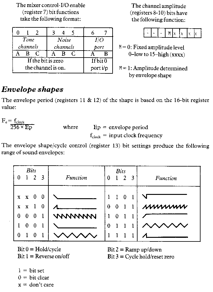
The noise generator frequency is controlled by a 5-bit noise period register, value 01H to 1FH (1 to 31), producing a frequency range of 4 Khz to 125 Khz. The mixer control register is a multi-function register that mixes the noise channels (defined by bits 3 to 5) and the tone channels (defined by bits 0 to 2) in all possible combinations to the input/output ports (bit 6 I/O, bit 7 port A or B).
The amplitude of a channel is controlled to one of sixteen fixed levels by the channel D/A converter register (lower 4 bits of the register) and only by setting the register to zero can the channel be turned off. The fifth bit of the amplitude control register is set to select the variable level output defined by the envelope generator.
The envelope generator comprises three registers, two provide the frequency variation and the third the format of the envelope. The frequency is determined by counting down the 16-bit value of the coarse and fine envelope registers range 0001H to FFFFH (1 to 65535). The shape and cyclic pattern of the envelope is defined by the lower 4 bits of the shape register (the amplitude register setting the level), the four bits provide for combinations of hold/cycle, reverse cycle on/off, ramp up/down and cycle hold pattern/reset to zero.
Parallel data I/O
The I/O register in the PSG is not associated with sound production, it provides a register to transfer 8-bit parallel data to and from the CPU bus to the I/O port A, there is no affect on any of the PSG's other functions.
Data is written to a peripheral device from the bus using the following steps:
Once data have been loaded into the register, the data remains until further data is loaded,
the system is reset, or the register is switched to input mode.
Data is read from a peripheral device to the bus with the following steps:
The register follows signals applied to the port, only by reading will the data be transferred to the bus.
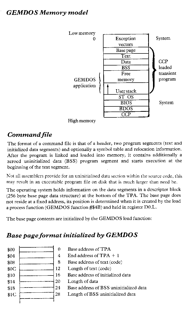
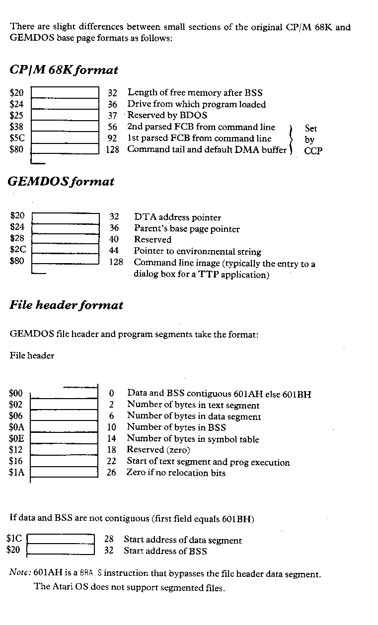
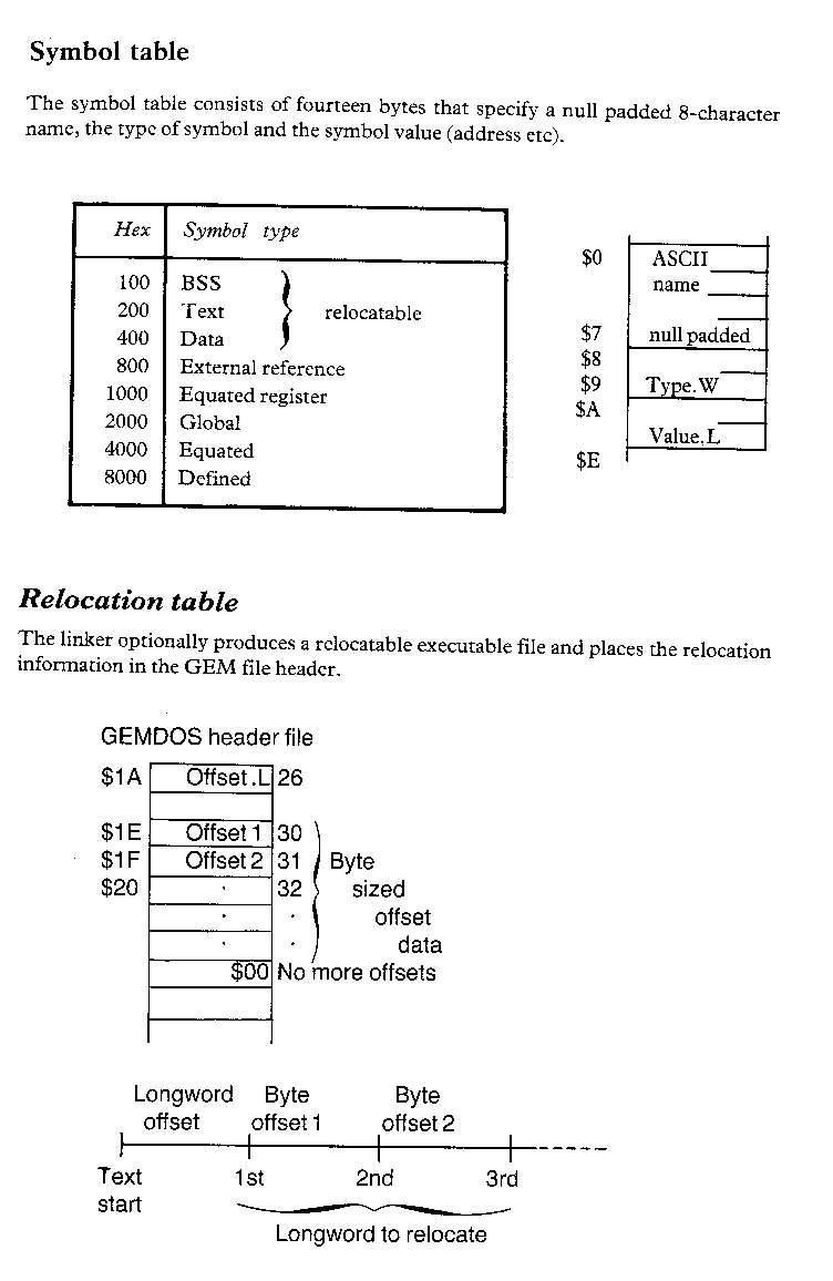
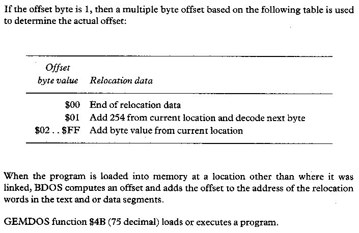
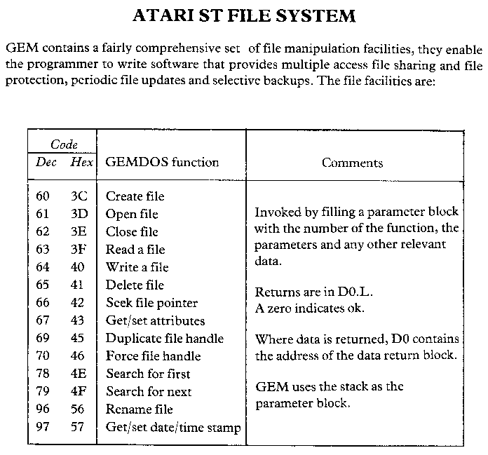
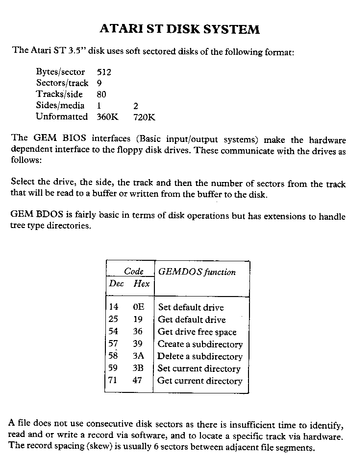
The ST contains device dependant input/output utilities that handle the interface between the device independent routines and the hardware, the ST BIOS and GEM BIOS utilities are supplemented by the A-line primitives which provide rapid screen control.
The GEM type BIOS handles the input/output to the peripheral devices: parallel port, RS232 port, console, MIDI interface and intelligent keyboard. There is also a basic disk read/write to sector and a facility to check that the disk has not been removed or replaced.
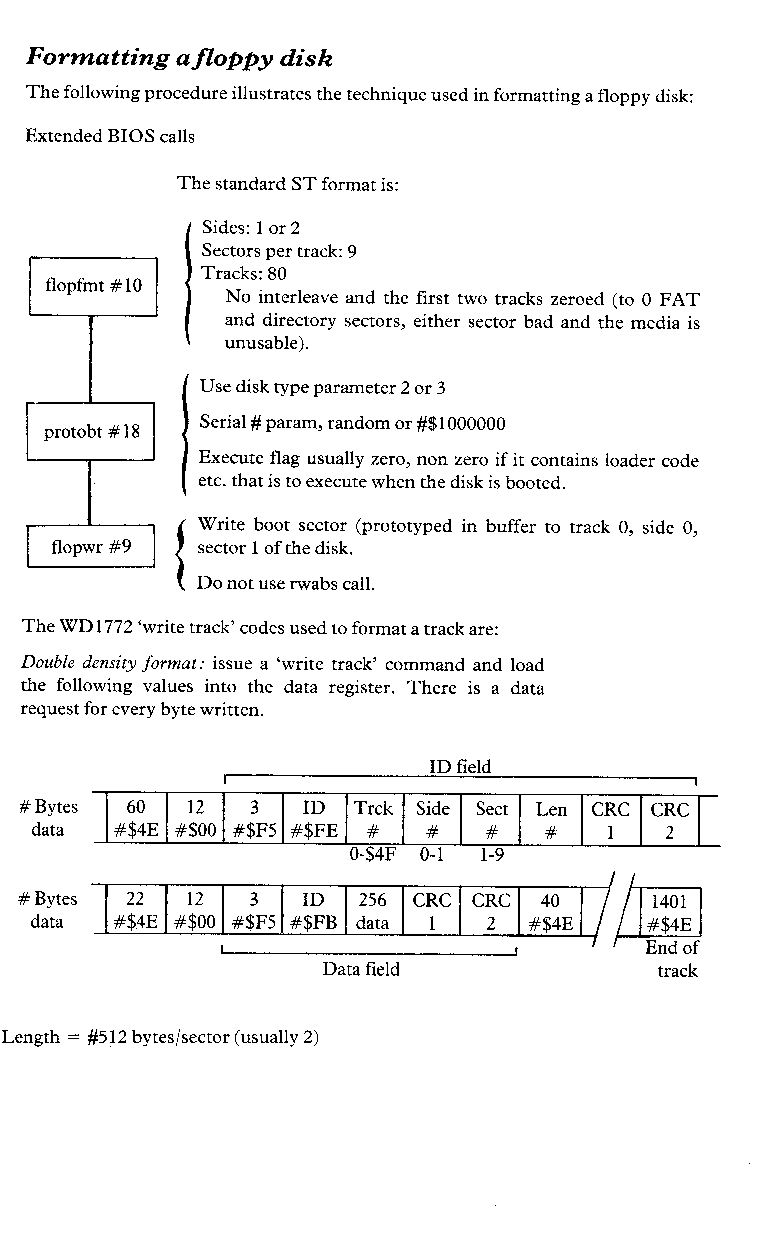
The ST extended BIOS also controls the input/output to the midi interface, intelligent keyboard, console and disk read/write, but additionally includes the control of a mouse, joysticks, sound and of the screen colours; the disk facility is augmented by format.
The A-line routines are the VDI graphic primitives which are not program transportable and therefore included here, they enable control of the mouse and pixel-line-sprite-screen graphics.
The operating system provides the machine code programmer with access to the interrupt handler.
Every fiftieth of a second control is transferred from the operating system to a routine at the address designated in the system variables at $68 (104 decimal), the system interrupt handler (vertical blank interrupts). The handler provides a timing facility, sets the screen parameters and current device driver installation and entry points.
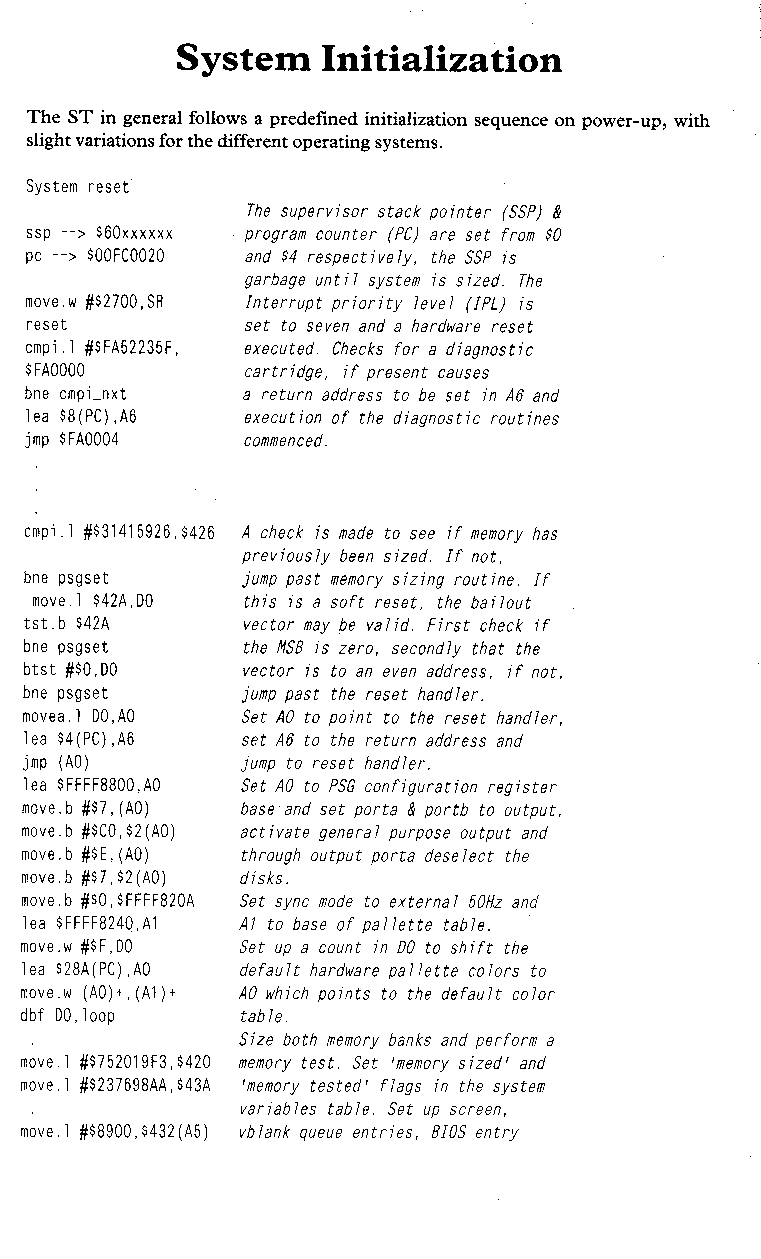
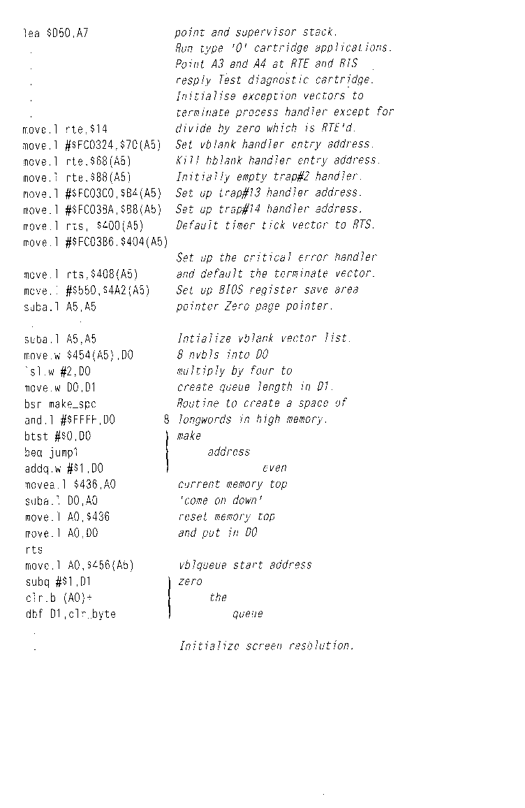
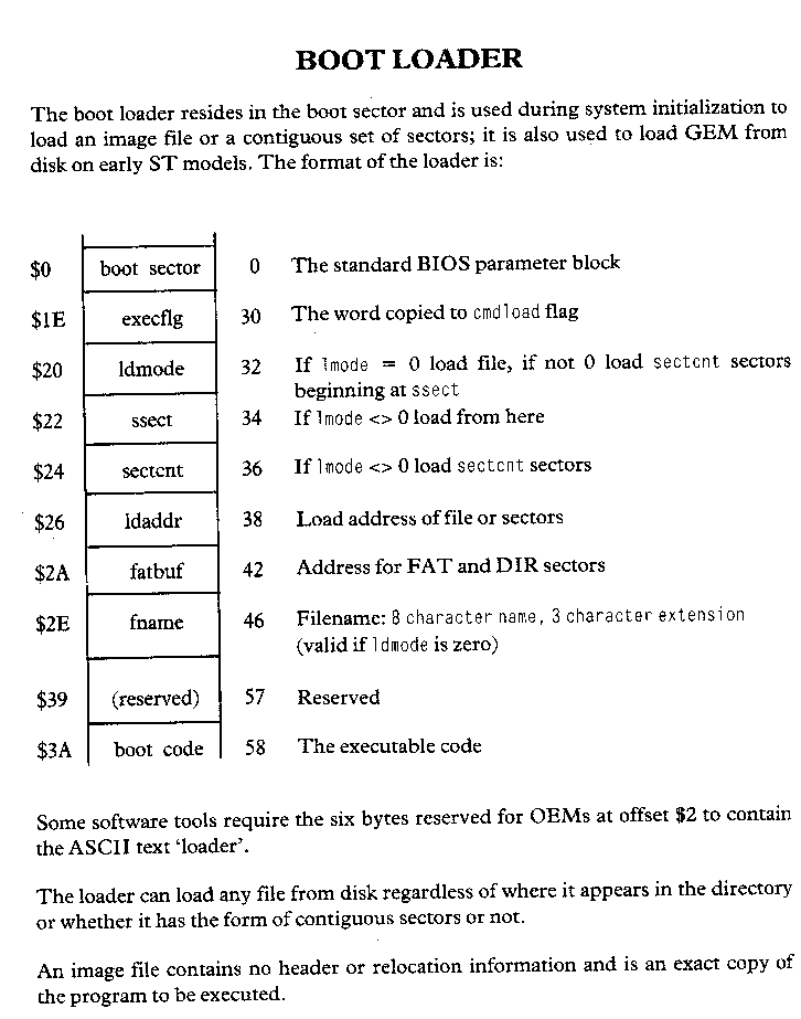
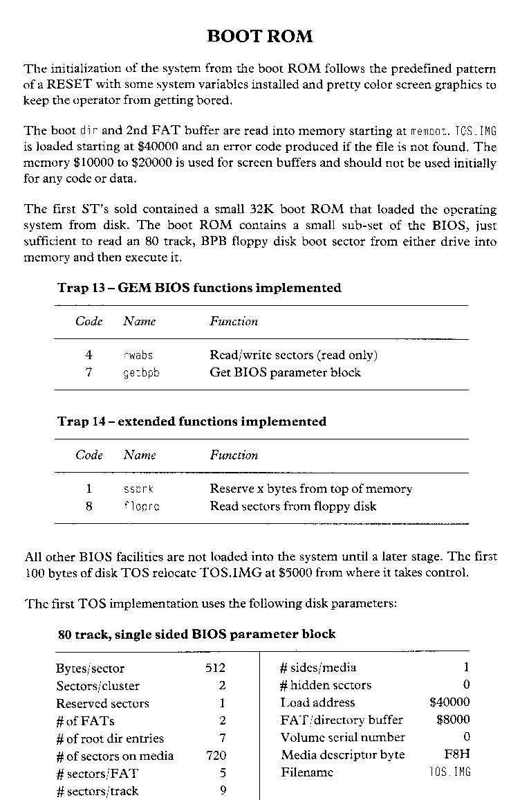
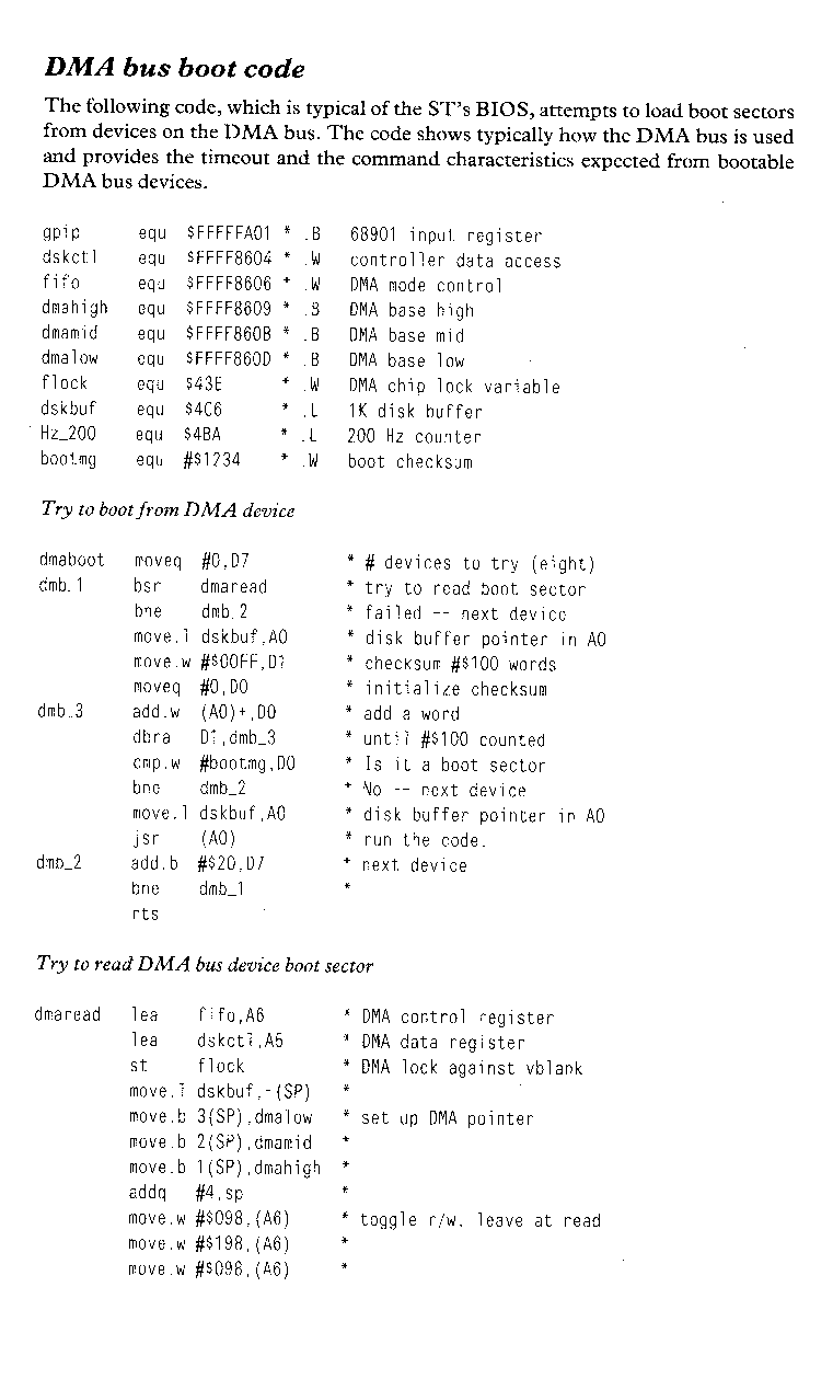
The ST supports serial and parallel communications through dedicated RS232 and parallel ports, and permits two further communication channels to be opened through the MIDI and DMA ports.
The serial RS232 communication port accommodates hardware data control based on the PSG I/O port A, RTS and DTR outputs, and the MFP MK68901, CTS, DCD and RI inputs, and Xon/Xoff software data protocol at transmit and receive baud rates in the range 50 to 19200 baud. The port is generally used to interface with a printer, modem or another computer. The MFP is located at $FFFA00 (16775680) and the PSG at $FF8814 (16746610).
The general purpose parallel port interface provides bi-directional 8 bit communications for printer operation. The port is based on the MFP MK68901 (busy control), the PSG I/0 port A bit 5 (strobe control) and the PSG I/O port B (data transfer). The control is limited to a busy signal, acknowledge is not supported and data transfer is at a typical rate of 4000 bytes/s.
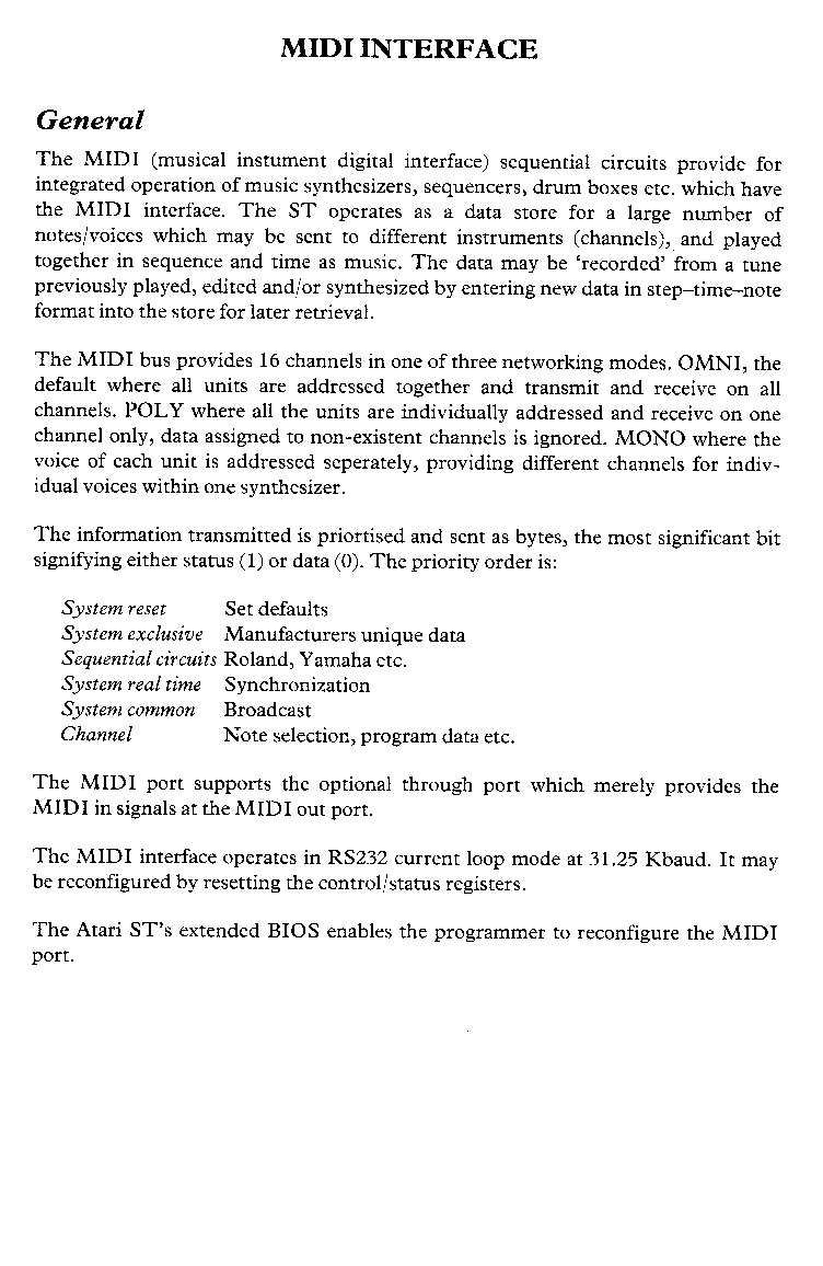
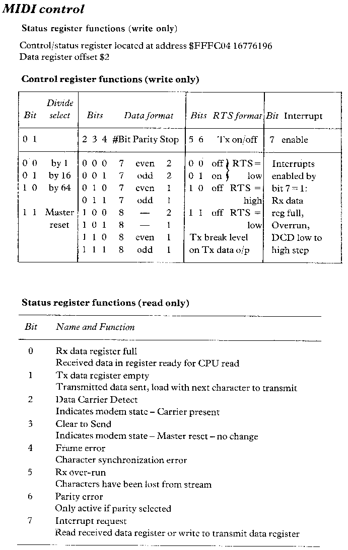
The MIDI interface provides an asynchronous, current loop, serial data (one start bit, eight data bits and one stop bit) communications channel at 31.25 Kbaud. The MC6850 port controller may be reconfigured for most forms of RS232 interface via the control/status register situated at address $FFFC04 (16776196).
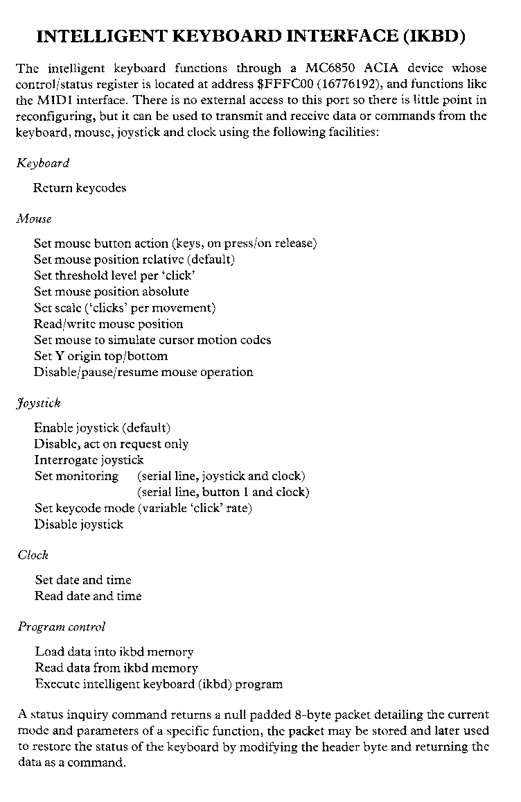
The intelligent keyboard interface is also controlled by an MC6850 ACIA, but there is no external access provided to the port, which is of limited use other than accessing the ikbd command set; for reading and or writing to the clock, joysticks, mouse and perhaps reconfiguring the keyboard.
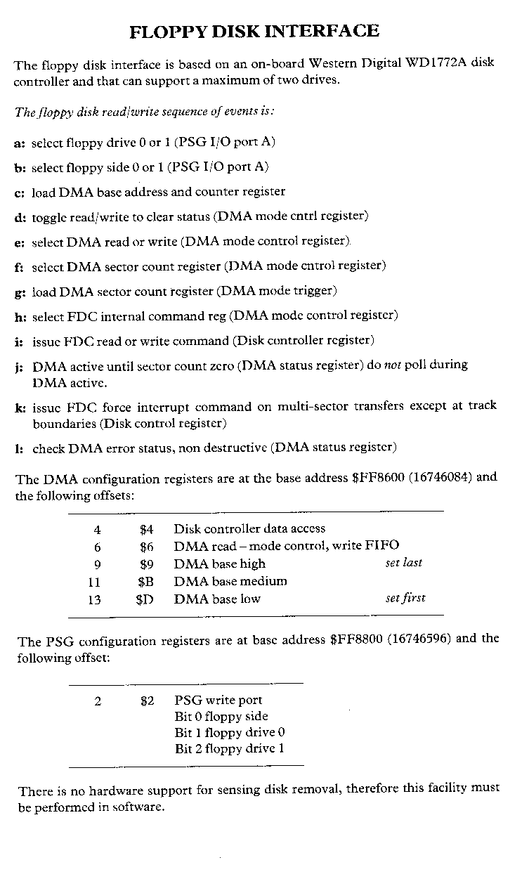
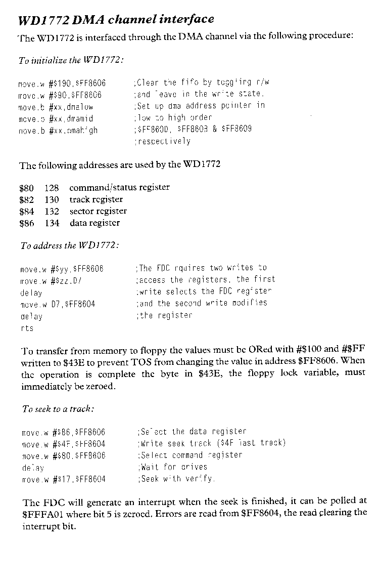
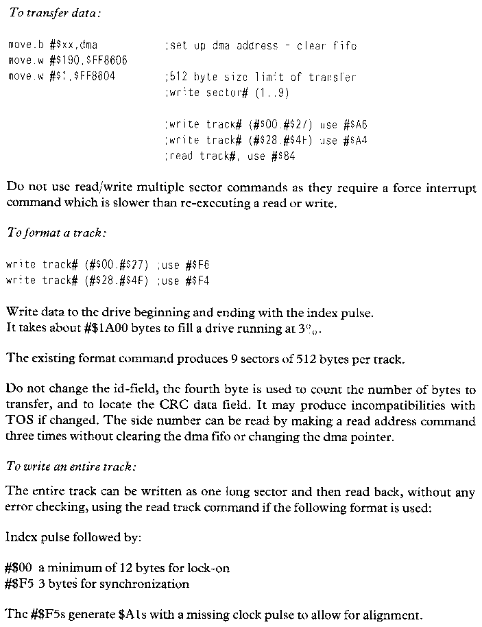
The floppy disk interface is based on the Western Digital WD1772A disk controller and is limited to supporting two drives.
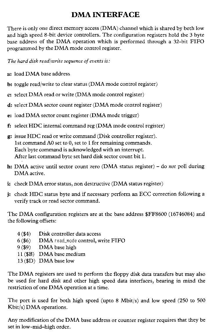
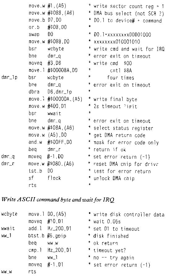
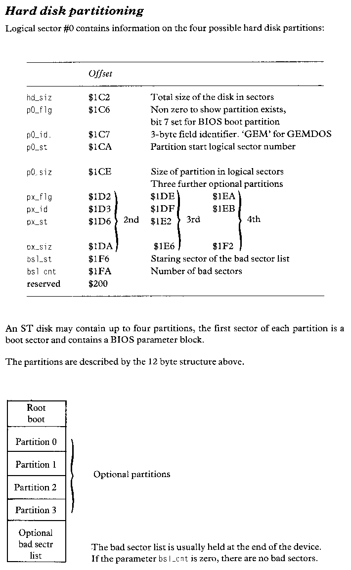
The DMA interface is provided by an ULA device, access is through the control/status configuration registers at $FF8600 (16746084) et seq.
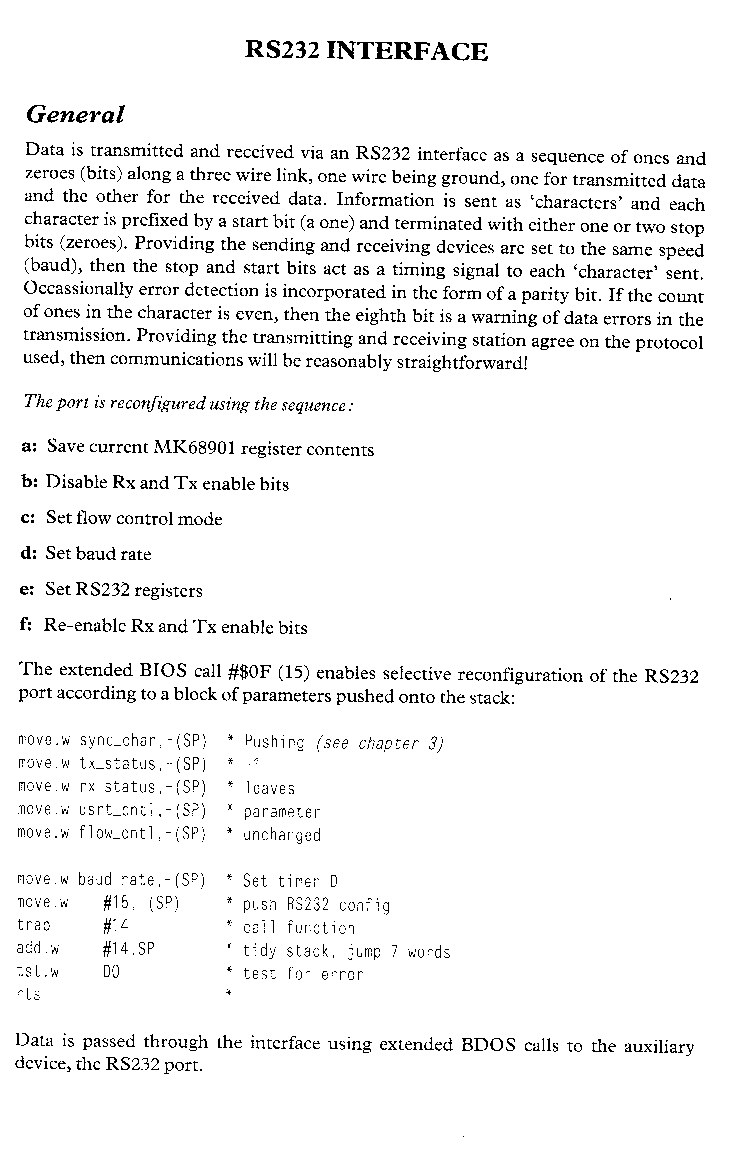
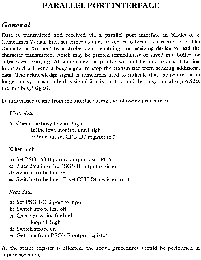
The keyboard scancodes do not maintain complete compatibility with IBM PC key scancodes. Appendix D provides the major differences due to the non-availability of certain keys on the ST keyboard. The additional ST keys are mapped into unused CTRL and ALT function scancodes.
To detect CTRL_ and ALT_ function key combinations, execute a BDOS or BIOS get char call followed by a BIOS kbshft call (#$0B).
